page 35/41
• If the burner head is damaged,
it should be replaced
• The electrode aluminium heads or ceramic
bases are damaged, they should be replaced
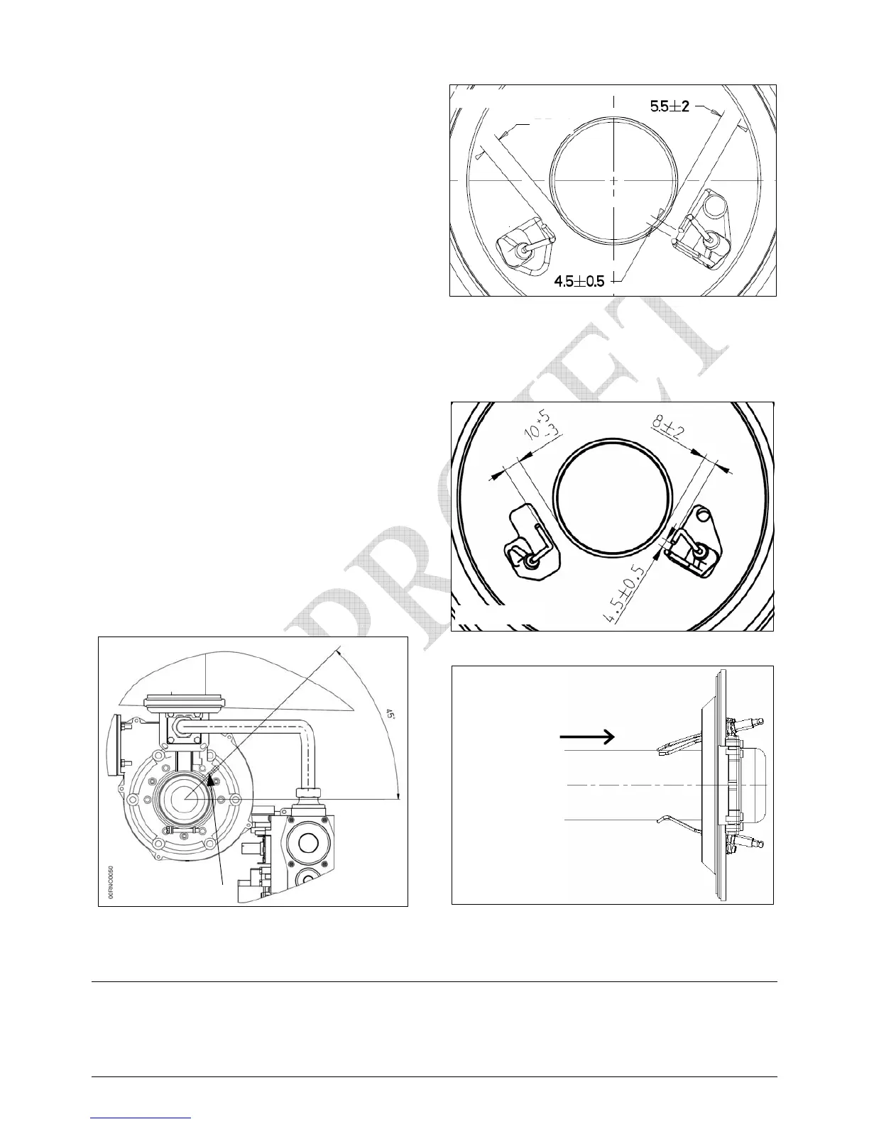
• Replace the burner in the position shown on
the drawings alongside
• Re-connect gas, air and micro-tubes
• Re-house the controller
• Switch on the electrical supply
• B ring the boiler into action, checking the
burner operation and combustion efficiencies
• Replace the front cover of the boiler
•
•
•
8.2. Draining the boiler
• Close the heating flow and return valves
• Open the safety valve to release the pressure
• Release the automatic air vent
• Connect a hose pipe to the drain valve and drain the boiler contents
Position of the air tapping on the pressure
diaphragm (VF 100 )
location of burner electrodes VF 100
view from F
VF burner
View from inside the combustion chamber
F
location of the burner electrodes
VF 60 Æ A = 5,5 +/- 2
view from F
A