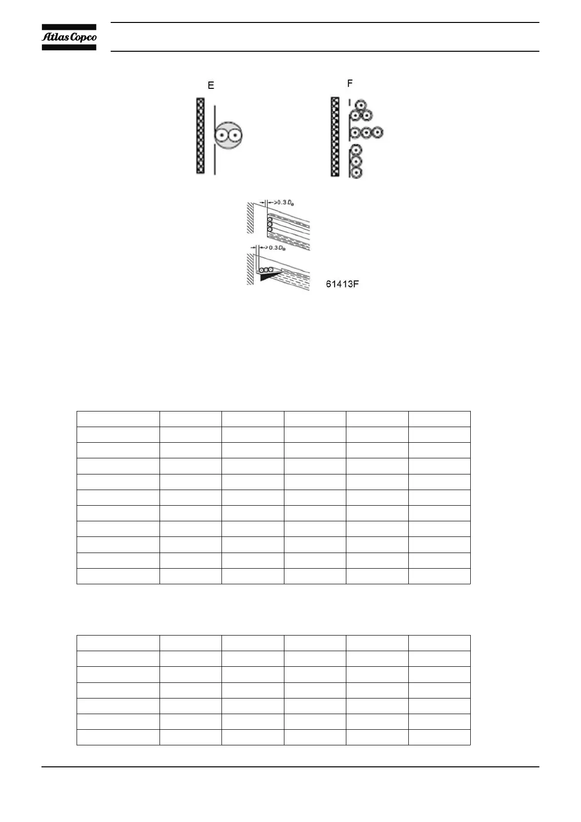
Installation method E or F, according table B.52.1;
Single-core or multi-core cables, touching in free air;
Clearance to wall not less than 0,3 times cable diameter for method E or one cable diameter for
method F.
Maximum allowable current in function of the ambient temperature for installation method E
(Multi-core cables with 3 loaded conductors and maximum conductor temperature 90 °C)
Cable section 30 °C 40 °C 45 °C 50 °C 55 °C
25 mm² < 127 A < 116 A < 110 A < 104 A < 97 A
35 mm² < 158 A < 144 A < 137 A < 130 A < 120 A
50 mm² < 192 A < 175 A < 167 A < 157 A < 146 A
70 mm² < 246 A < 224 A < 214 A < 202 A < 187 A
95 mm² < 298 A < 271 A < 259 A < 244 A < 226 A
120 mm² < 346 A < 315 A < 301 A < 284 A < 263 A
150 mm² < 399 A < 363 A < 347 A < 327 A < 303 A
185 mm² < 456 A < 415 A < 397 A < 374 A < 347 A
240 mm² < 538 A < 490 A < 468 A < 441 A < 409 A
300 mm² < 621 A < 565 A < 540 A < 509 A < 472 A
Maximum allowable current in function of the ambient temperature for installation method F
(Single-core cables with 3 loaded conductors and maximum conductor temperature 90 °C)
Cable section 30 °C 40 °C 45 °C 50 °C 55 °C
25 mm² < 135 A < 123 A < 117 A < 110 A < 103 A
35 mm² < 169 A < 154 A < 147 A < 139 A < 128 A
50 mm² < 207 A < 188 A < 180 A < 170 A < 157 A
70 mm² < 268 A < 244 A < 233 A < 220 A < 204 A
95 mm² < 328 A < 298 A < 285 A < 269 A < 249 A
120 mm² < 383 A < 349 A < 333 A < 314 A < 291 A
Instruction book
66 9829 3178 63

 Loading...