OVERVIEW
Equipment description
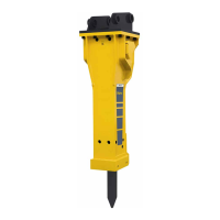
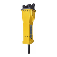
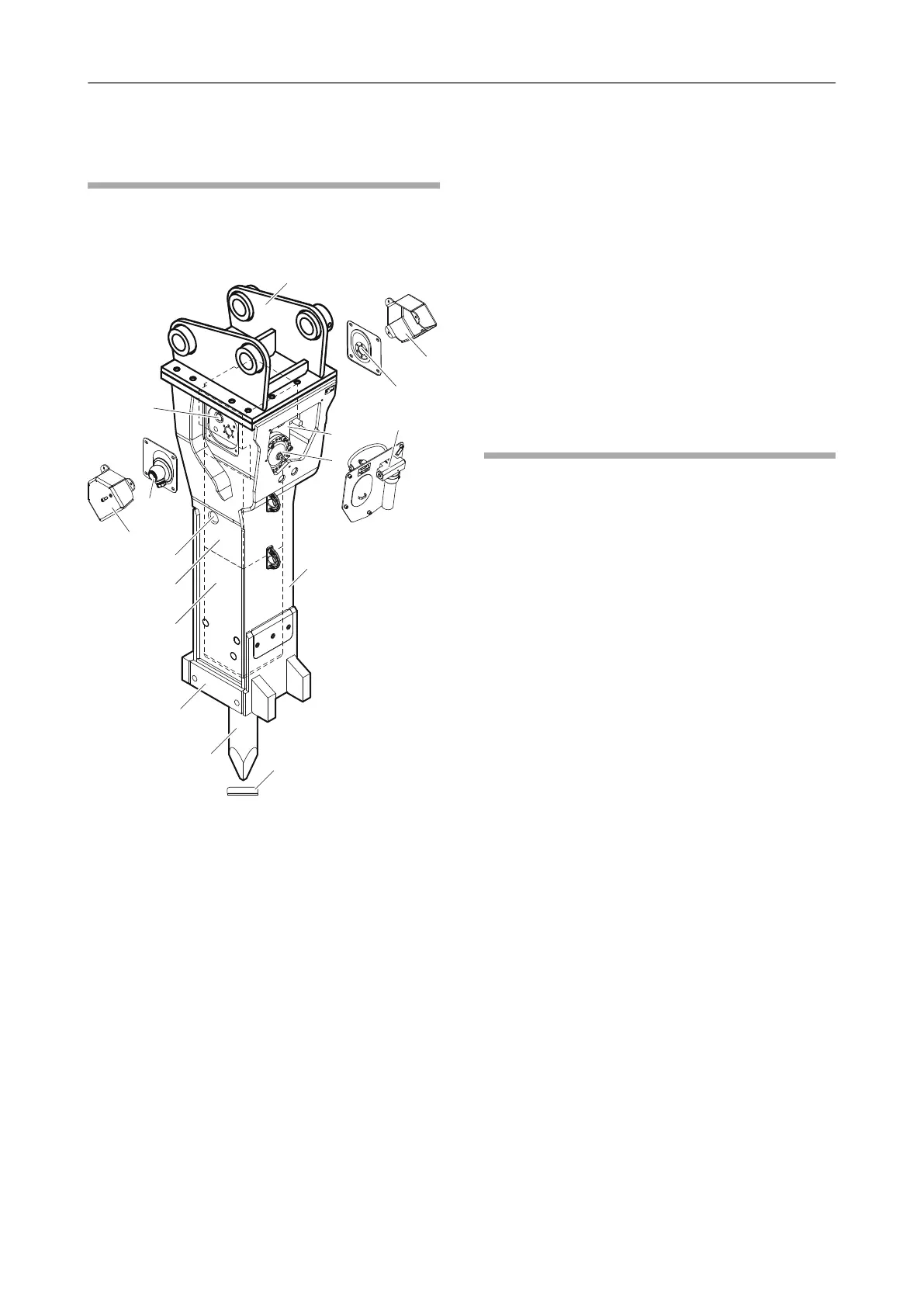
The picture gives an overview of the main parts and
components of the hydraulic attachment. Actual
details may differ.
A. The hydraulic breaker is connected to the
carrier by the adapter plate. The adapter plate
is not included in the scope of supply of the
hydraulic breaker.
B. Tank line »T«
C. Automatic lubrication system ContiLube
®
II
D. The cylinder cover houses the nitrogen gas
(N
2
) filled piston accumulator and the control
mechanism.
E. The HP-accumulator compensates pressure
variations in the hydraulic system.
F. The breaker box protects the percussion unit.
G. Working tool aperture protective cap
H. The working tool can be replaced as required.
The working tool is not included in the scope
of supply of the hydraulic breaker.
I. The DustProtector system prevents dust from
entering the percussion compartment (only on
the DP version).
J. The working tool is retained in the lower
breaker part.
K. The percussion piston is guided in the
cylinder.
L. StartSelect valve
M. Pressure line »P«
N. Non-return valve of percussion compartment
ventilation
O. The swivel joint covers protect the swivel
joints.
Function
The operation of a hydraulic breaker is described in
a greatly simplified version below:
The pressure line »P« supplies oil at the operating
pressure of the carrier to the hydraulic breaker. The
tank line »T« returns the oil to the tank of the carrier.
The HP-accumulator compensates pressure
variations in the hydraulic system.
The percussion piston moves up and down in the
cylinder. When the percussion piston is in its lower
position, it impacts the working tool. The percussion
energy is transferred to the material to be broken via
the working tool.
15© 2012 Atlas Copco Construction Tools GmbH | No. 3390 5096 01 | 2012-04-26
Original instructions
OVERVIEWHB 3100, 3100 DP, 3600, 3600 DP, 4100, 4100 DP,
4700, 4700 DP
 Loading...