16
ORV 10 - ORV 12 - ORX 10 - ORX 12
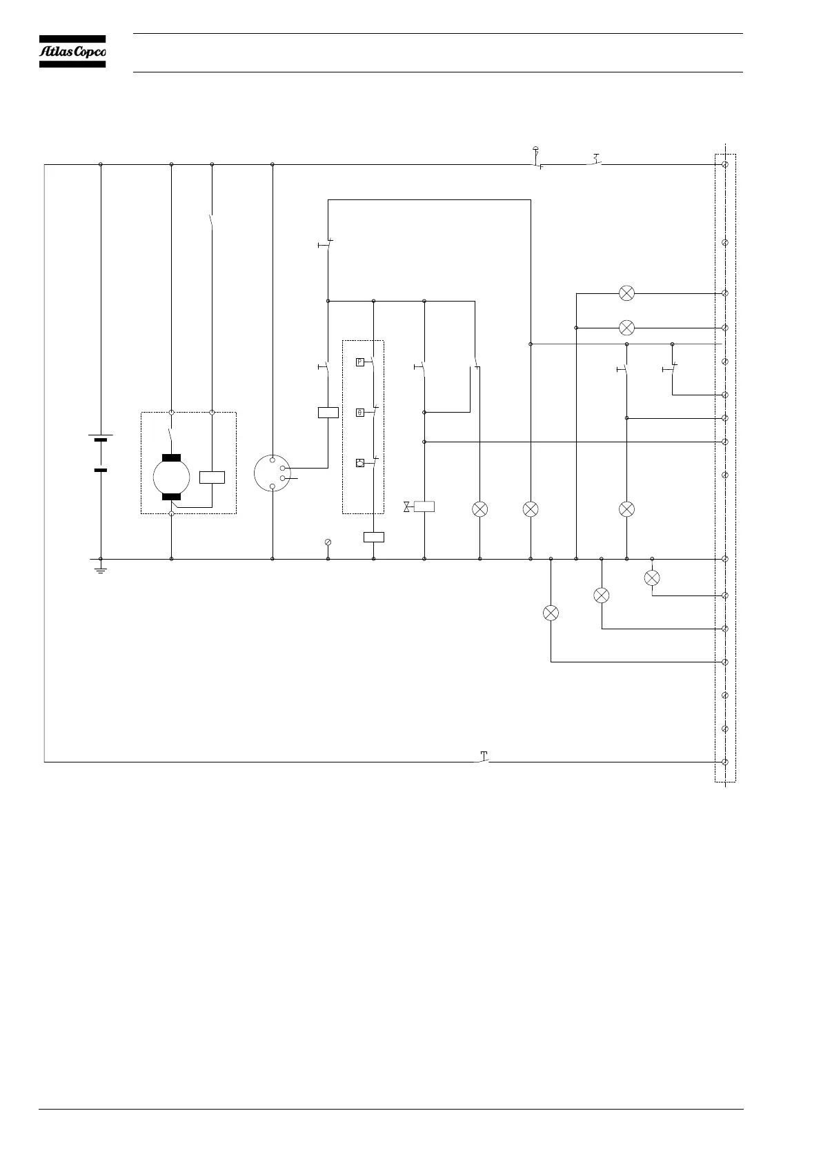
2.8 ELECTRICAL SYSTEM
Fig. 2.5 Typical Customer Installation for mechanically controlled diesel engine
G10: Battery M10: Starter Motor
G20: Battery PS10: Pressure Switch - Oil Pressure Protection
G30: Alternator S10: Switch - Emergency Stop
GNDv: Connection Vessel GND S20: Switch - Main Power ON/OFF
H10: Lamp - Airfilter Warning Indicator S30: Switch - Compressor Load Signal
H20: Lamp - Element Temperature Shutdown Indicator S40: Switch - Compressor Noload Signal
H30: Lamp - Compressor Loaded Indicator S50: Switch - Engine Stop Signal
H40: Lamp - Ready To Start Indicator S60: Switch - Engine Start Signal
H50: Lamp - Engine Shutdown Indicator / Override Indicator S70: Switch - Override Switch
H60: Lamp - Oiltronix™ Failure Indicator (Option) S80: Switch - Draining Acknowledged (Option)
H70: Lamp - Oiltronix™ Warning Indicator (Option) TS10: Temperature Switch
H80: Lamp - Oiltronix™ Draining Indicator (Option) X1: Connector
K10: Relay - Starter Motor Activation Y10: Solenoid Valve - Engine Fuel Stop Solenoid
K20: Relay - Engine Shutdown
LS10: Level Switch - Coolant Level Protection
12/24VDC
+
-
G10
M10
K10
K0
K0
G30
K20
GNDv
K10
S60
S50
PS10
S70
S10 S20
1
2
3
4
5
7
8
9
10
11
12
13
14
15
16
6
X1
K20
H10
H20
S30
H50
Y10
H40 H30
H80
S80
H70
H60
S40
30
87 87a
TS10
LS10
B+
D+
W+
B-
M
Connect to
Compressor Drive GND
+
-
G20
 Loading...