- 54 -
Block mode
When the block mode is selected, the unit is locked
for certain actions. This means that it cannot start the
gen-set or perform any breaker operations.
To change the running mode from the display, the
user will be asked for a password before the change
can be made. It is not possible to select ‘block mode’
when running feedback is present.
The purpose of the block mode is to make sure that
the gen-set does not start for instance during
maintenance work. If the digital inputs are used to
change the mode, then it is important to know that the
input configured to block mode is a constant signal.
So, when it is ON the unit is in a blocked state, and
when it is OFF, it returns to the mode it was in before
block mode was selected.
4.4.4.5 Standard applications
In the Qc4002™ MkII module 9 application types can
be selected. A combination of each application type
with the running mode results in a specific
application.
Depending on the application the user has to connect
extra wirings to terminal blocks X25. These terminal
blocks can be found inside the control box on a DIN-
rail. We refer to the circuit diagram 9822 0996 18/02
for the correct connections.
Island operation
This application is possible in combination with
SEMI-AUTO mode or AUTO mode. The internal real
time clock timer can only be used in AUTO
This operation type is selected for installations with
one or more generators, but always without the Mains
(= stand-alone). In practice up to 16 generators can be
installed in parallel.
Installation wirings
– Terminals X25.10/X25.11 have to be linked. The
module always needs a feedback signal from the
Mains Breaker MB. In Island mode there is no
MB in the system. In this case the MB opened
signal is simulated with this link.
– The busbar sensing lines have to be wired to the
corresponding control module inputs. Place
bridge between:
• X25.33 (L1) => X25.3
• X25.34 (L2) => X25.4
• X25.35 (L3) => X25.5
• X25.36 (N) => X25.6
(The busbar = power cables between GB and load)
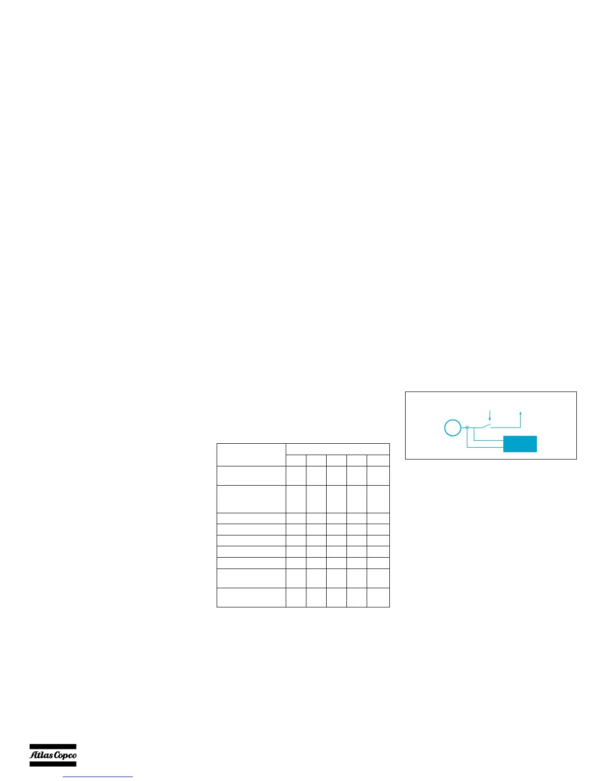
Gen-set mode Running mode
Auto Semi Test Man Block
Automatic Mains
Failure (no back sync.)
X(X)X X X
Automatic Mains
Failure (with back
sync.)
X(X)X X X
Island operation X X X X
Fixed power/base load X X X X X
Peak shaving X X X X X
Load take over X X X X X
Mains power export XXXX X
Multiple gen-sets, load
sharing
XX X X
Multiple gen-sets,
power management
X(X)X X X
G
Qc4002
LOAD
Generator
breaker
 Loading...


