2
INSTALLATION HARDWARE
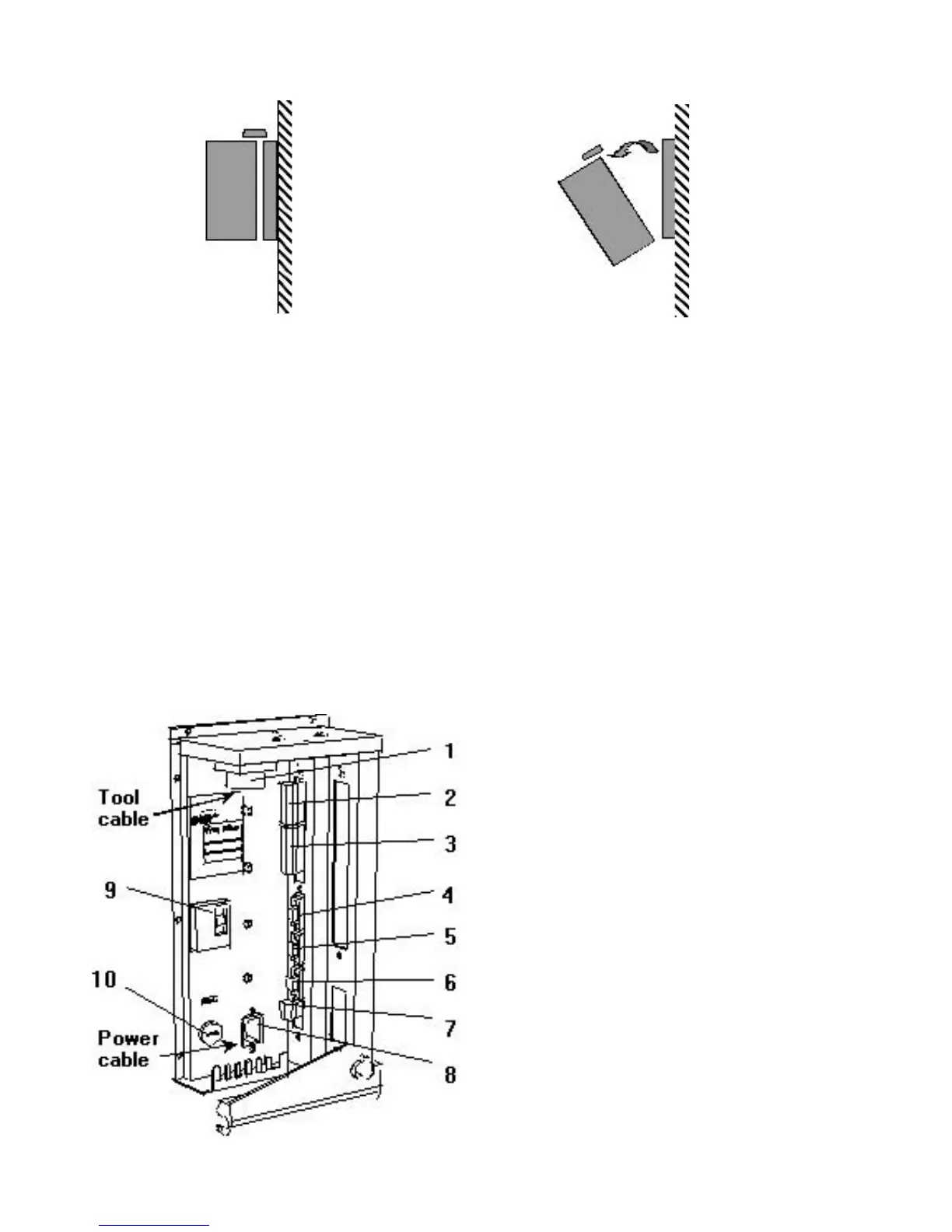
1. Open the lock mechanism (see figure 1)
2. Open the DS Drive by pulling it (see figure 2)
3. Connect the tool cable, power cable etc. (see figure 3)
4. Check so that the GFI is switched on
5. Close the DS Drive and lock it
6. Connect the power cable to a power supply 115/230 V
7. Turn the power on
IMPORTANT! Whenever replacing a tool, always turn the power off.
Figure 1 Figure 2
1. Tool cable connector
2. Digital inputs. Only for D312
3. Relay outputs
4. RS 232
5. I/O bus. Only activated
for D312
6. I/O bus. Only activated
for D312
7. Remote control
8. Main power connector
9. Ground fault interrupter,
GFI, 30 mA
10. Main fuse. 6.3 x 32 mm –
Slow Blow,15/20/25 A
Figure 3