Product Description 13
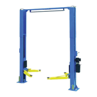
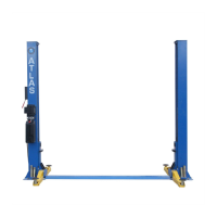
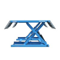
Kwik Bay
platforms (1) each equipped with N.2 ramps (2) which can be locked as the
platform extensions, placed on the ground by means of base frames (3).
Platforms are linked to the base frame by means of a scissor lifting system. The
lifting system of each platform is composed of arms (4) and a cylinder (5).
Motion is transmitted by a lever system, from the cylinders to the lever arm (6).
Lowering and lifting are carried out by operation of the control unit (7) which is
removable.
The mechanical safety locks operated by pneumatic cylinders are installed at
each base and controlled by the control panel. The lift is equipped with a bolster
beam in front to keep the two platforms level during lifting and lowering.
N.2 wheels (8) can be installed on the lifts so that the lift can be mobile by
means of a hook on the power unit carriage.
 Loading...