14
ATtiny15L
1187H–AVR–09/07
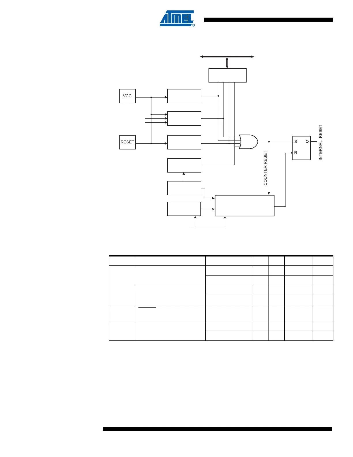
Figure 12. Reset Logic
Note: 1. The Power-on Reset will not work unless the supply voltage has been below V
POT
(falling).
Table 4. Reset Characteristics (V
CC
= 5.0V)
(1)
Symbol Parameter Condition Min Typ Max Units
V
POT
Power-on Reset Threshold
Voltage (rising)
BOD disabled 1.0 1.4 1.8 V
BOD enabled 1.7 2.2 2.7 V
Power-on Reset Threshold
Voltage (falling)
(1)
BOD disabled 0.4 0.6 0.8 V
BOD enabled 1.7 2.2 2.7 V
V
RST
RESET Pin Threshold
Voltage
– – 0.85 V
CC
V
V
BOT
Brown-out Reset Threshold
Voltage
(BODLEVEL = 1) 2.3 2.7 2.9 V
(BODLEVEL = 0) 3.4 4.0 4.3 V
MCU Status
Register (MCUSR)
Brown-out
Reset Circuit
BODEN
BODLEVEL
Delay Counters
CKSEL[1:0]
CK
TIMEOUT
WDRF
BORF
EXTRF
PORF
DATA BU S
Tunable Internal
Oscillator
Watchdog
Oscillator
Watchdog
Timer
Reset Circuit
Power-on Reset
Circuit

 Loading...


