55
ATtiny15L
1187H–AVR–09/07
Calibration Byte The ATtiny15L has a one-byte calibration value for the internal RC Oscillator. This byte
resides in the high byte of address $000 in the signature address space. To make use of
this byte, it should be read from this location and written into the normal Flash Program
memory. At start-up, the user software must read this Flash location and write the value
to the OSCCAL Register.
Programming the Flash Atmel’s ATtiny15L offers 1K byte of In-System Reprogrammable Flash Program mem-
ory and 64 bytes of in-System Reprogrammable EEPROM Data memory.
The ATtiny15L is shipped with the On-chip Flash program and EEPROM data memory
arrays in the erased state (i.e., contents = $FF) and ready to be programmed.
This device supports a High-voltage (12V) Serial Programming mode and a Low-voltage
Serial Programming mode. The +12V is used for programming enable only, and no cur-
rent of significance is drawn by this pin (less than 100
µA). The Low-voltage Serial
Programming mode provides a convenient way to download program and data into the
ATtiny15L inside the user’s system.
The Program and Data memory arrays in the ATtiny15L are programmed byte-by-byte
in either Programming mode. For the EEPROM, an auto-erase cycle is provided within
the self-timed write instruction in the Low-voltage Serial Programming mode.
During programming, the supply voltage must be in accordance with Table 24.
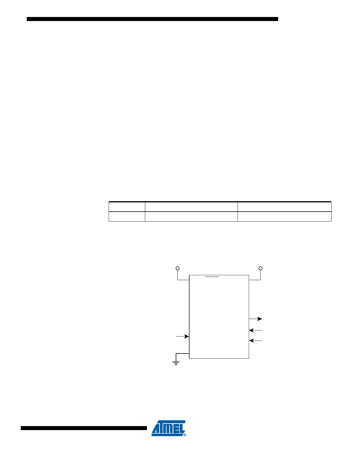
High-voltage Serial
Programming
This section describes how to program and verify Flash Program memory, EEPROM
Data memory, Lock bits and Fuse bits in the ATtiny15L.
Figure 30. High-voltage Serial Programming
Table 24. Supply Voltage during Programming
Part Low-voltage Serial Programming High-voltage Serial Programming
ATtiny15L 2.7 - 5.5V 4.5 - 5.5V
PB5 (RESET)
PB3
GND
VCC
PB2
PB1
PB0
SERIAL DATA OUTPUT
SERIAL INSTR. INPUT
SERIAL DATA INPUT
SERIAL CLOCK INPUT
11.5 - 12.5V 4.5 - 5.5V
ATtiny15/L

 Loading...


