C-3
3. Push the trimmed compensation ring, then tube fitted inside
the IIT Container into the tube holder. Secure them with Thread
Ring 15 (using Wrench ST.00.03.000) and Screws (16) (to ar-
rest the tube transverse offset). Double check Screws (16)
are not overtightened! Use primer coat to lock the ring and the
screws.
C-3. ASSEMBLY WORK INSIDE SCOPE
1. First, you will need to calculate the needed thickness of the set
of compensation rings.
There are two methods of calculation:
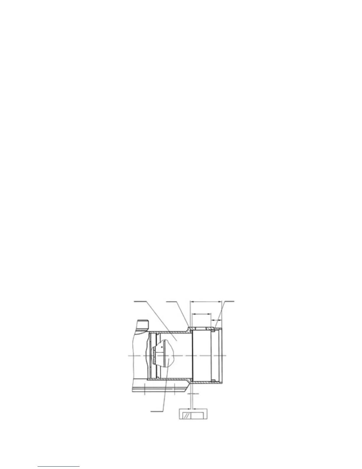
a) Set collimator and riflescope focus adjustment knob for
Figure C4). Push Tube Holder Assembly (11) inside the
scope body, first, without compensation rings’ set, allow-
ing for 2.5-3mm vacant space from the support lip inside
the body which the assembly’s end would normally rest
against. Solder the IIT Container with the tube inside to
the plate. By turning Thread Ring (12) you may smoothly
move the tube holder inside the scope body towards the
objective lens assembly’s location. Af ter the image reach-
es its grain (in focus), secure this position of the tube
holder assembly inside the scope body with Screw (17).
FIGURE C-4
11 2 D
E
F
X
IIT
0.03
12