Chapter 2
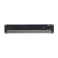
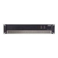
Front & rear panel
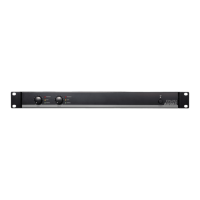
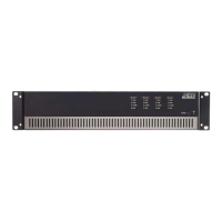
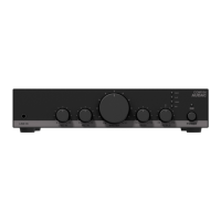
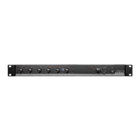
Front panel overview
ON
100
PROTECT
CLIP
SIGNAL
100
PROTECT
CLIP
SIGNAL
EPA502
Front panel description
Volume control knobs:
These volume control knobs allow level adjustment for each individual channel.
Indicator LED’s:
These LED’s indicate the operation of the corresponding amplifier channel. A signal indicator,
clip indicator and protect indicator are available for each channel.
The signal indicator illuminates in green colour when the signal level exceeds the -20 dB level.
The clip indicator illuminates in yellow colour when the channel is working at maximum level.
To ensure the best signal-to-noise ratio, illumination of this indicator should only occur
at peak levels. When it illuminates frequently, the channel output will be overdriven and a
distorted ‘clipping’ sound occurs on the output.
The protect indicator illuminates in red colour when any overload, thermal overheating or
other fault is detected. It also illuminates for several seconds when powering on the amplifier
and slowly fades out when switching off the amplifier. When the protect LED is illuminated,
no signal will be available on the output.
Power switch with LED:
A power switch allows to turn the amplifier on and off. The indicator LED next to the power
switch indicates the current status of the amplifier. When operational, it illuminates in blue
colour. When switched to standby (energy-saving) mode, the power LED will illuminate in
orange colour. The amplifier switches automatically to standby mode when no input signal
is available for about 30 seconds and instantly switches back to operation when any signal
is detected.