Chapter 3
Connecting the Amplifier
NOTE
Make sure the power is switched OFF when any change is made to the connections of
the amplifier.
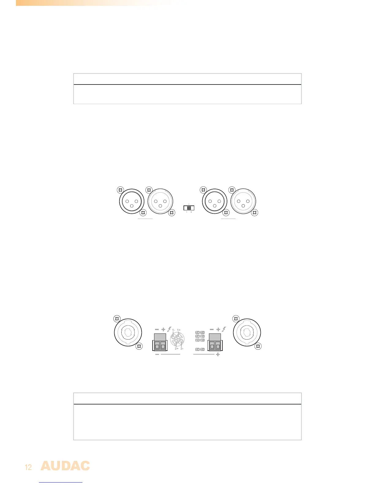
Input connections
The signal input connections are implemented using balanced XLR connectors with link
output connectors. Each channel is provided with an individual input connection whereto
the signal coming from the audio source of pre-amplifier shall be fed, while the link output
connectors can be used for linkthrough to other amplifiers.
Bridge Parallel
Stereo
MODE
CH 1
An operation mode switch allows switching the channels between stereo, bridge and parallel
mode.
Output connections
The loudspeaker output connections are implemented using both Speakon compatible and
terminal block connectors. Depending of the application requirements, the appropriate
connection method can always be used.
CH 2
Speakon 2 Speakon 1
CH 1:
Bridge
:
CH 2:
Speakon 1
CH 1
SPEAKER OUTPUT
CH 2:
Speakon 2
The ‘Speakon 1’ output connector carries signals for both both channels, allowing connection
for both channels through a single 4-core cable or bridge mode connections.
ATTENTION
Do not make any direct connection with line transformers on the loudspeaker outputs
of the amplifier. When using in combination with line transformers units, make sure the
used transformers are designed for being used in combination with Class-D amplifiers
(containing integrated decoupling network).