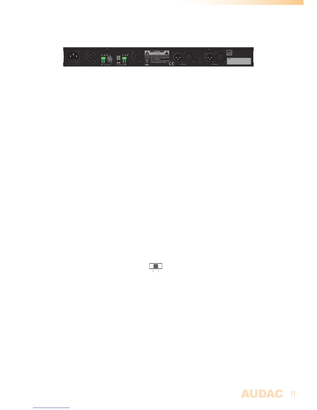
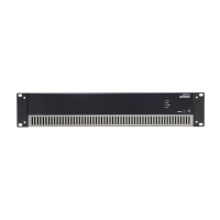
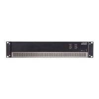
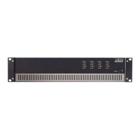
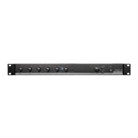
Rear panel overview
Bridge Parallel
Stereo
MODE
CH 1
AC Input
230V 50/60Hz, 220W
Fuse: T10AL/250V
CH 2
Speakon 2 Speakon 1
CH 1:
Bridge
:
CH 2:
Speakon 1
Bridge
CH 1
SPEAKER OUTPUT
INPUTLINK
CH 2
INPUTLINK
CH 2:
Speakon 2
EPA502
AUDAC
PROFESSIONAL POWER AMPLIFIER
Rear panel description
AC Power inlet with fuse:
The mains power supply has to be applied to this AC power inlet. The connection is made
by an IEC C14 power connector and is fitted with a fuse. When replacing the fuse, make
sure that the value of the replacement fuse matches the value of the original fuse. (EPA152:
T5AL/250V - EPA252: T6.3AL/250V - EPA502: T10AL/250V )
Loudspeaker connections:
The loudspeaker output connections for each channel are implemented using both Speakon
compatible and terminal block connectors. Depending of the application requirements, the
appropriate connection method can always be used. A detailed description for connecting
loudspeakers in the most appropriate way for each application can be found in the next
chapter ‘Connecting the amplifier’.
Input connections:
The signal input connections are implemented using balanced XLR connectors with link
output connectors. Each channel is provided with an individual input connection whereto
the signal coming from the audio source of pre-amplifier shall be fed, while the link output
connectors can be used for linkthrough to other amplifiers.
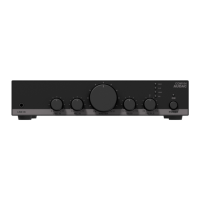
Operation mode switch:
An operation mode switch allows switching between stereo, bridge and parallel mode.
Bridge Parallel
Stereo
MODE
It is default configured in stereo mode (center position) whereby each amplifier channel is
fed with an individual input signal. In bridge mode (left position), the power of both channels
is merged for delivering double power to a single load. In parallel mode (right position), the
input is linked, feeding the identical signal to both channels.