System 10 Installation and Operation
4
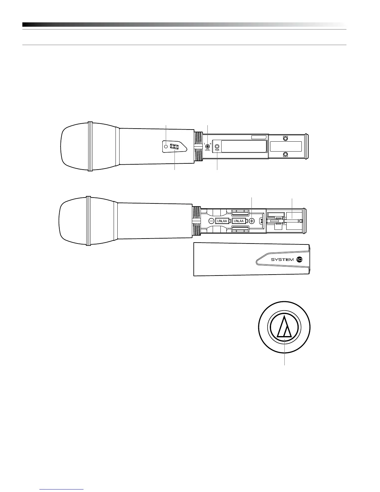
ATW-T1002 Transmitter Setup Controls and Functions
Battery Selection and Installation
Two alkaline AA batteries are recommended. When inserting the battery,
observe correct polarity as marked inside the battery compartment.
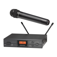
Figure C — ATW-T1002 Handheld Transmitter
Handheld Transmitter Battery Installation
1. While holding the upper part of the transmitter body just below the
ball-screen, unscrew the lower body cover and slide it off to expose
the battery compartment (Fig. C).
2. Carefully insert two fresh AA alkaline batteries, observing
polarity markings.
3. Screw the body back together. Do not overtighten.
Handheld Transmitter Battery Condition Indicator
After the batteries are installed, press and hold the Power/Mute switch
on the bottom of the handheld transmitter until the indicator LED turns
green. If the indicator LED does not light up when the Power/Mute
switch is pressed, the batteries are installed incorrectly or they are
dead. The indicator LED will ash to show low-battery condition.
Handheld Transmitter Mute Function
With the transmitter on, a slight touch of the power switch will toggle
between muted and unmuted operation. Red indicator LED shows
muted operation. Green indicator LED shows unmuted operation.
Handheld Transmitter Pairing Switch
Used to complete pairing sequence. See page 6.
Handheld Transmitter Level Control
Used to set microphone level. See page 6.
Handheld Transmitter Screwdriver
Used to adjust Level Control. See page 6.
Level Control
System ID Display Pairing Switch
Screwdriver
Power/Mute Switch
Battery
Compartment
Power / Battery / Mute
Status Indicator
Handheld Transmitter System ID Display
Shows System ID. See page 6. Note: System ID is an identical number
assigned to a paired receiver and transmitter for identication purposes.
When Power is applied, the System ID Display on the transmitter glows
bright and then turns off to conserve battery life. To turn the System ID
Display back on, mute and unmute the transmitter.
 Loading...