System 10 Installation and Operation
5
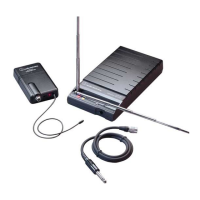
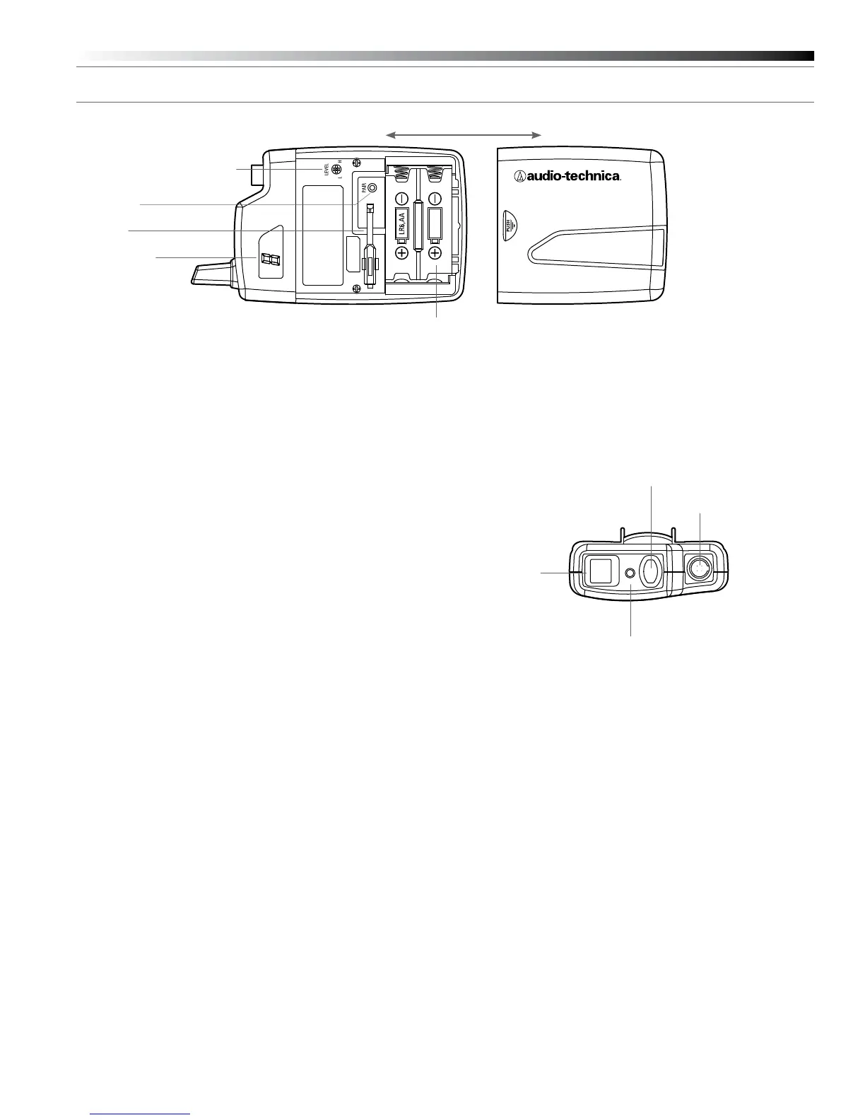
Figure D — ATW-T1001 UniPak
®
Transmitter
UniPak
®
Transmitter Battery Installation
1. Slide off the battery cover.
2. Carefully insert two fresh AA alkaline batteries, observing polarity
markings.
3. Replace the battery cover (Fig. D).
UniPak
®
Transmitter Power/Mute/Battery Indicator
After the battery is installed, press and hold the Power/Mute button
until the indicator LED turns green (Fig. E). If the indicator LED does not
light up when the power button is pressed, the batteries are installed
incorrectly or they are dead. The indicator LED will ash to show low-
battery condition.
UniPak
®
Transmitter Mute Function
With the transmitter on, a slight touch of the Power/Mute button will
toggle between muted and unmuted operation. Red indicator LED shows
muted operation. Green indicator LED shows unmuted operation.
UniPak
®
Transmitter Input Connection
Connect an audio input device (microphone or guitar cable) to the
audio input connector on the top of the transmitter. A number of
Audio-Technica professional microphones and cables are available
separately, pre-terminated with a UniPak
®
input connector (see
www.audio-technica.com).
UniPak
®
Transmitter Antenna
The UniPak
®
transmitter includes a permanently-attached antenna. If
the received signal is marginal, experiment with different transmitter
positions on your body or instrument; or try repositioning the receiver.
Do not attempt to remove, replace or change the length of the
transmitting antenna.
UniPak
®
Transmitter Pairing Switch
Used to complete pairing sequence. See page 6.
UniPak
®
Transmitter Microphone/Instrument Level Control
Used to set microphone/instrument level. See page 6.
UniPak
®
Transmitter Screwdriver
Used to adjust Level Control. See page 6.
UniPak
®
Transmitter System ID Display
Shows System ID. See page 6. Note: System ID is an identical number
assigned to a paired receiver and transmitter for identication purposes.
When power is applied, the System ID Display on the transmitter glows
bright and then turns off to conserve battery life. To turn the System ID
Display back on, mute and unmute the transmitter.
LR6,AA
Figure E — UniPak
®
Transmitter
Antenna
Input
Connector
Power/Mute
Button
System ID Display
Screwdriver
Microphone / Instrument Level Control
Pairing Switch
Indicator LED
(Power/Mute/Battery)
Battery Compartment
 Loading...