INSTALLATION and POWER
page 1 – 5
R-55 / Mar 2003
Power Supply
PS-6040 Power Supply
The R-55 console is powered by a model PS-6040 power supply.
Mount the PS-6040 power supply in a standard 19” equipment rack,
keeping in mind that adequate ventilation is necessary to prevent heat
build-up within the rack.
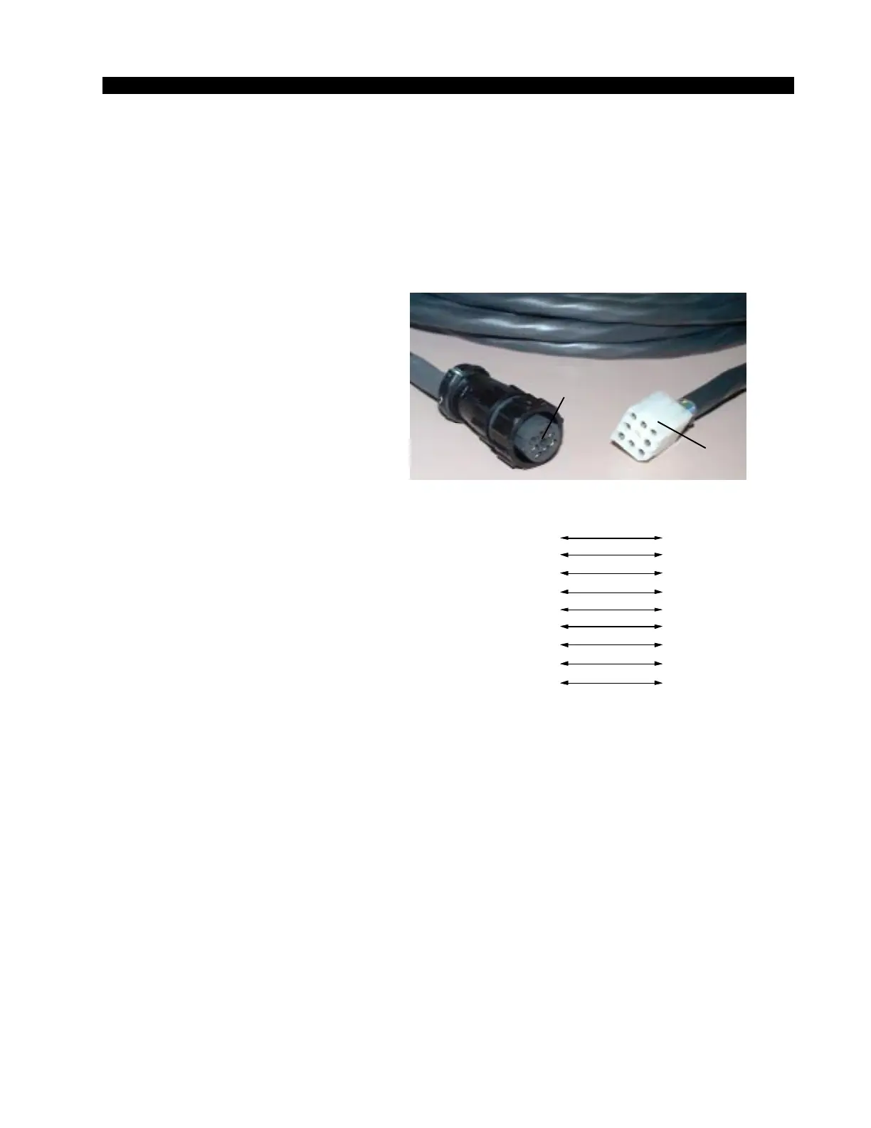
Once the supply is rackmounted, it
should be connected to the console
using the factory supplied cable. The
cable has two different types of 9-pin
connectors on its end: a plastic shell
connector that connects to the console’s
power supply connector, and a multi-
pin cable-mount connector that plugs
into the PS-6040 power supply. The
console’s power supply connector is
mounted on the right side of the con-
sole meterbridge rear.
Note that the power supply cable’s
9-pin female connector has to be ro-
tated until its locating pins match the
male connector on the power supply.
Do not force a connector on; it attaches
easily when properly aligned. Connect
the cable first to the console, then to the
rear of the rackmount power supply.
If you are using two supplies
(failsafe option), connect the long
power supply cable’s round power supply connector to the center
connector of the rackmount failsafe panel. Then connect one supply
with a short cable to either of the two remaining connectors on the
failsafe panel and connect the second supply with a short cable to the
last connector.
Note each power supply is fitted with a 3-wire grounded AC cord
that should be plugged into a "clean" AC power source, that is, an AC
source that feeds only the control room audio gear. This source should
be a separate feed from those powering lighting, air-conditioning, or
any other non-audio machinery. The third pin ground wire of the AC
source should be tied to the central system ground point. Note that
while the AC power cord ground wire terminates at the power supply
chassis, it does NOT connect to the R-55 console common; the console
itself must be grounded separately. (See previous section, "System
Ground".)
The power feed recom-
mended in the text is of-
ten installed and referred
to in studios as an “iso-
lated AC ground” outlet.
It is usually orange in
color.
If failsafe redundant sup-
plies have been ordered,
you will be installing two
units and an additional
rackmount panel.
Power Supply
End
Console
1
2
3
4
+5V Digital
+5V Digital
Digital
ommon
Audio
ommon
PIN
7
4
6
1
PIN
9-pin Connector
Female
9-pin Connector
Female
Power Supply End
Console End
5
6
7
8
N
-18V
Audio
ommon
+40V Phantom
5
3
8
9
9
+18V
2
ORG
YEL
GRN
BLK
N/C
BLU
BRN
VIO
PS Cable Pinou
RED
ORG
YEL
GRN
BLK
N/C
BLU
BRN
VIO
RED
R-55 / Aug 2003