page 3 – 2
R-55 / Mar 2003
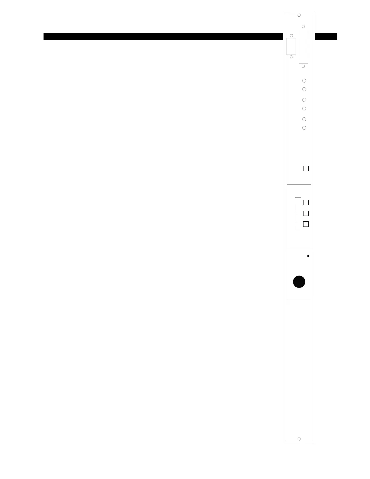
OUTPUT MODULE
Output Module
(OM-55)
Module Overview
The master output module handles the console’s Program, Audi-
tion, and Mono/Pre outputs. All outputs are calibrated with recessed
front panel multi-turn trimpots.
Each R-55 console has two pairs of left-right VU meters: PGM and
SWT (switched) located on the console’s meterbridge. The switched
meter follows the SELECT switching, allowing the console operator to
meter PGM, AUD, MONO and PRE, and an external stereo line signal
(analog, +4dBu balanced), which may be brought into the module on
its DB-25 connector.
The OM-55 module houses the master Cue LED. Whenever Cue is
activated anywhere on the console this LED will illuminate and the
CUE signal will automatically appear on the switched VU meter pair.
When cue is de-activated, the switched meter pair goes back to its
previously selected signal.
The CUE master level control sets the level of the console’s cue
signal.
Whenever CUE is activated elsewhere on the console (stereo line inputs
or for studio talkback) its signal will appear at the console’s built-in cue
speaker mounted in the meterbridge. Depending on how the CRS-55
module has been programmed, cue can also interrupt the control room
monitor speakers. The way Cue interrupts the control room/studio outputs is
determined by PCB-mounted dipswitch. See “Cue Interrupt” on 4-3 page.
The OM-55 module also generates the console’s monitor signals,
which feed the Control Room/Studio module.
All user wiring to and from the OM-55 module takes place at
DB-25 and DB-9 multi-pin connectors mounted on top of the module
and located underneath the hinged meterbridge. All analog audio is
+4dBu balanced. Pinout drawings on pages 3-5 show all wiring
connections at a glance.
AA
AA
UU
UU
DD
DD
TT
TT
RR
RR
II
II
MM
MM
LL
LL
TT
TT
MM
MM
EE
EE
TT
TT
EE
EE
RR
RR
SS
SS
OM
MM
MM
OO
OO
NN
NN
OO
OO
TT
TT
RR
RR
II
II
MM
MM
LL
LL
TT
TT
SS
SS
WW
WW
II
II
TT
TT
CC
CC
HH
HH
EE
EE
DD
DD
AA
AA
UU
UU
DD
DD
RR
RR
TT
TT
RR
RR
TT
TT
EE
EE
XX
XX
TT
TT
PP
PP
GG
GG
MM
MM
WW
WW
##
##
00
00
22
22
77
77
00
00
00
00
22
22
AA
AA
PP
PP
GG
GG
MM
MM
MM
MM
OO
OO
NN
NN
OO
OO
//
//
SS
SS
OO
OO
UU
UU
RR
RR
CC
CC
EE
EE
11
11
00
00
99
99
88
88
77
77
66
66
44
44
33
33
22
22
11
11
00
00
55
55
CC
CC
UU
UU
EE
EE
BB
BB
II
II
//
//
OO
OO
AA
AA
II
II
//
//
OO
OO
PP
PP
RR
RR
EE
EE
PP
PP
RR
RR
EE
EE
CC
CC
UU
UU
EE
EE