page 3 – 3
R-55 / Mar 2003
OUTPUT MODULE
Hook-Ups
As stated before, all user wiring to and from the OM-55 modules takes
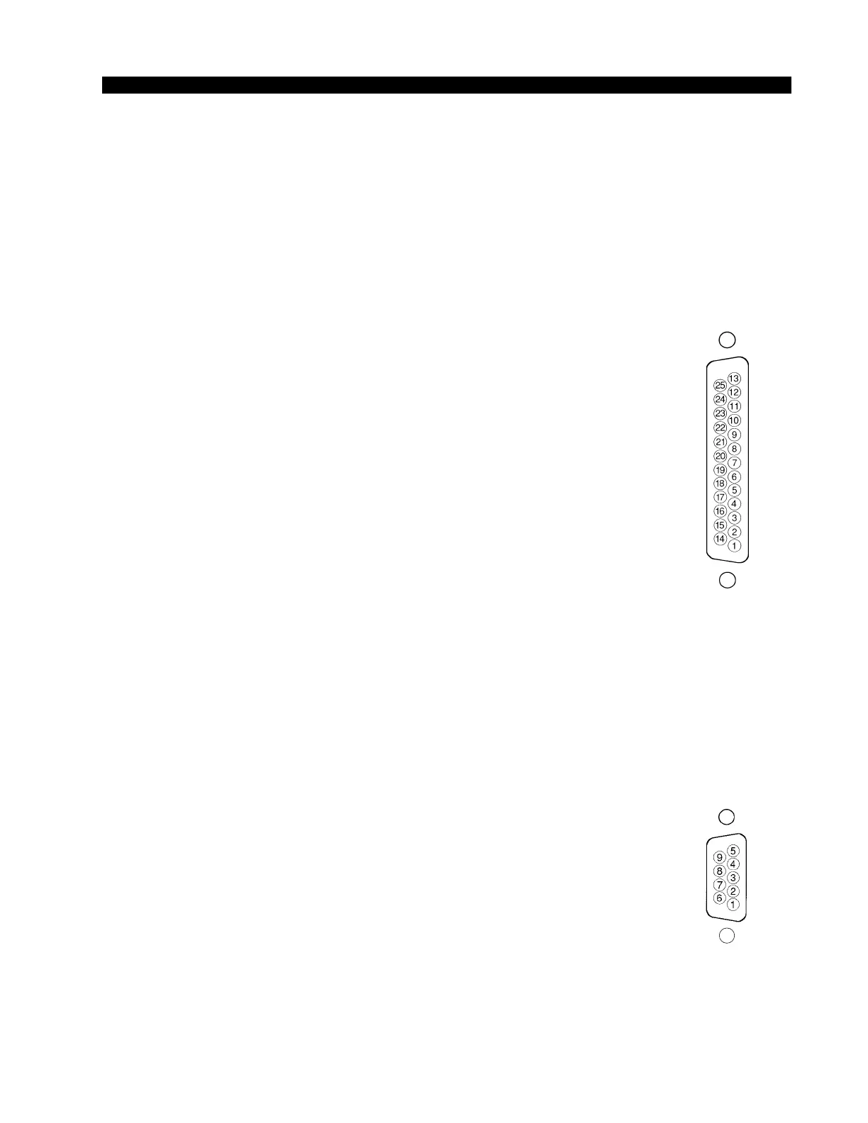
place at DB-25 and DB-9 multi-pin connectors on the top of module.
DB-25 Connector – Audio
Handles External input and Program, Audition, Mono, and Pre outputs.
All signals are +4dBu balanced.
Pin 25 – PGM Lt Out SH
Pin 24 – PGM Lt Out HI
Pin 12 – PGM Lt Out LO
Pin 11 – PGM Rt Out SH
Pin 10 – PGM Rt Out HI
Pin 23 – PGM Rt Out LO
Pin 22 – AUD Lt Out SH
Pin 21 – AUD Lt Out HI
Pin 9 – AUD Lt Out LO
Pin 8 – AUD Rt Out SH
Pin 7 – AUD Rt Out HI
Pin 20 – AUD Rt Out LO
Pin 19 – MONO Out SH
Pin 18 – MONO Out HI
Pin 6 – MONO Out LO
Pin 5 – PRE Out SH
Pin 4 – PRE Out HI
Pin 17 – PRE Out LO
Pin 16 – EXT Lt In SH
Pin 15 – EXT Lt In HI
Pin 3 – EXT Lt In LO
Pin 2 – EXT Rt In SH
Pin 1 – EXT Rt In HI
Pin 14 – EXT Rt In LO
DB-9 Connector – Audio
Handles CUE output.
Pin 5 – CUE Out SH
Pin 4 – CUE Out HI
Pin 9 – CUE Out LO
DB-9 Connector — Control
Handles Tally 1 and Tally 2 control connections.
Pin 3 – Tally 1 N.O.
Pin 7 – Tally 1 Com.
Pin 6 – Tally 2 Com
Pin 1 – Tally 2 N.O.
Pins 2 and 8 - Audio Common
Typical DB-25
connector
Typical DB-9
connector