page 4 – 4
RD-12 / March 99
OUTPUT MODULES
AMP D Connector – Digital Outputs
Handles digital Program outputs (AES format)
Pin 10 – PGM AES Out SH
Pin 12 – PGM AES Out HI
Pin 11 – PGM AES Out LO
Master Output Module 2:
AMP A, B Connectors – Analog Audio
Includes Audition, Utility outputs and Audition insert points. All signals
are +4dBu balanced.
Pin 1 – AUD Lt Out SH
Pin 3 – AUD Lt Out HI
Pin 2 – AUD Lt Out LO
Pin 4 – AUD Rt Out SH
Pin 6 – AUD Rt Out HI
Pin 5 – AUD Rt Out LO
Pin 7 – UTIL Lt Out SH AMP A connector
Pin 9 – UTIL Lt Out HI
Pin 8 – UTIL Lt Out LO
Pin10 – UTIL Rt Out SH
Pin 12 – UTIL Rt Out HI
Pin 11 – UTIL Rt Out LO
Pin 1 – AUD Lt Insert Out SH
Pin 3 – AUD Lt Insert Out HI
Pin 2 – AUD Lt Insert Out LO
Pin 4 – AUD Rt Insert Out SH AMP B connector
Pin 6 – AUD Rt Insert Out HI
Pin 5 – AUD Rt Insert Out LO
Pin 7 – AUD Lt Insert In SH
Pin 9 – AUD Lt Insert In HI
Pin 8 – AUD Lt Insert In LO
Pin 10 – AUD Rt Insert In SH
Pin 12 – AUD Rt Insert In HI
Pin 11 – AUD Rt Insert In LO
AMP D Connector – Digital Outputs
Handles digital Audition and Utility outputs (AES format)
Pin 7 – UTIL AES Out SH
Pin 9 – UTIL AES Out HI
Pin 8 – UTIL AES Out LO
Pin 10 – AUD AES Out SH
Pin 12 – AUD AES Out HI
Pin 11 – AUD AES Out LO
Insert points are normally by-
passed at the factory. See “In-
sert Bypass” (preceding page) if
you intend to use these points.
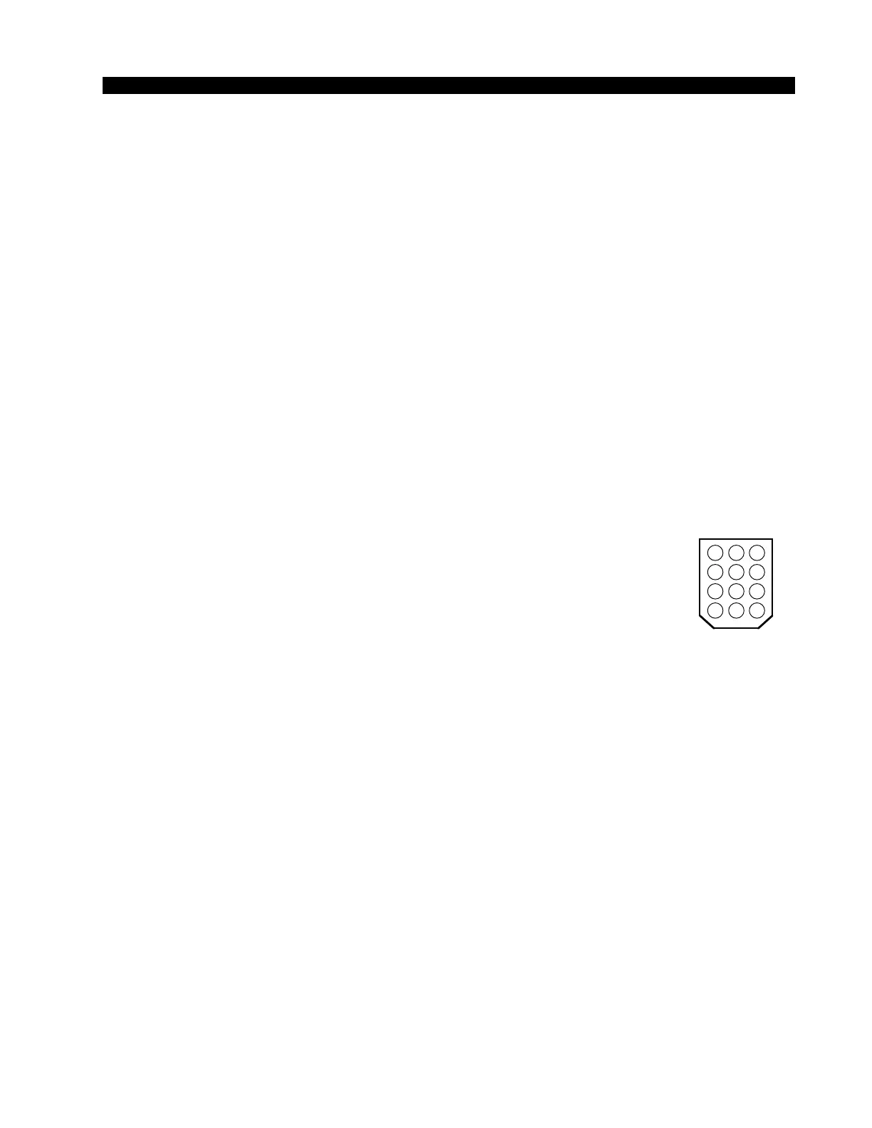
Key diagram showing
back of typical 12-pin I/O
connector plug, with pin
numbers oriented as they
would be seen while wir-
ing. Beveled corners cor-
respond to PCB mounted
mating sockets.
5 46
8 79
11 1012
2 13