page 11 – 4
RD-12 / March 99
LINE PRESELECTOR MODULE
LSD-5 POWER CONNECTIONS (AMP C, D)
Pin 1 - -V (LSR-500 DB-25 Pin 25)
Pin 2 - -V (LSR-500 DB-25 Pin 12)
Pin 3 - -V (LSR-500 DB-25 Pin 24)
Pin 4 - -V (LSR-500 DB-25 Pin 11)
Pin 5 - +V (LSR-500 DB-25 Pin 23)
Pin 6 - +V (LSR-500 DB-25 Pin 10)
Pin 7 - +V (LSR-500 DB-25 Pin 22)
Pin 8 - +V (LSR-500 DB-25 Pin 9)
Pin 9 - Audio Ground (LSR-500 DB-25 Pin 21)
Pin 10 - Audio Ground (LSR-500 DB-25 Pin 8)
Pin 11 - Audio Ground (LSR-500 DB-25 Pin 20)
Pin 12 - Audio Ground (LSR-500 DB-25 Pin 7)
Pin 1 - Digital Ground (LSR-500 DB-25 Pin 19)
Pin 2 - Digital Ground (LSR-500 DB-25 Pin 6)
Pin 3 - Digital Ground (LSR-500 DB-25 Pin 18)
Pin 4 - Digital Ground (LSR-500 DB-25 Pin 5)
Pin 5 - Digital Ground (LSR-500 DB-25 Pin 17)
Pin 6 - Digital Ground (LSR-500 DB-25 Pin 4)
Pin 7 - +5V Digital (LSR-500 DB-25 Pin 16)
Pin 8 - +5V Digital (LSR-500 DB-25 Pin 3)
Pin 9 - +5V Digital (LSR-500 DB-25 Pin 15)
Pin 10 - +5V Digital (LSR-500 DB-25 Pin 2)
Pin 11 - +5V Digital (LSR-500 DB-25 Pin 14)
Pin 12 - +5V Digital (LSR-500 DB-25 Pin 1)
LSR-500 Audio Inputs
These are for analog stereo (+4dBu balanced) and digital (AES)
signals; there are three DB-25 input connectors on the chassis rear:
ANALOG AUDIO INPUTS 1-4:
Pin 25 – Line 1 Lt In SH
Pin 24 – Line 1 Lt In HI
Pin 12 – Line 1 Lt In LO
Pin 11 – Line 1 Rt In SH
Pin 10 – Line 1 Rt In HI
Pin 23 – Line 1 Rt In LO
Pin 22 – Line 2 Lt In SH
Pin 21 – Line 2 Lt In HI
Pin 9 – Line 2 Lt In LO
Pin 8 – Line 2 Rt In SH
Pin 7 – Line 2 Rt In HI
Pin 20 – Line 2 Rt In LO
Pin 19 – Line 3 Lt In SH
Pin 18 – Line 3 Lt In HI
Pin 6 – Line 3 Lt In LO
Pin 5 – Line 3 Rt In SH
Pin 4 – Line 3 Rt In HI
Pin 17 – Line 3 Rt In LO
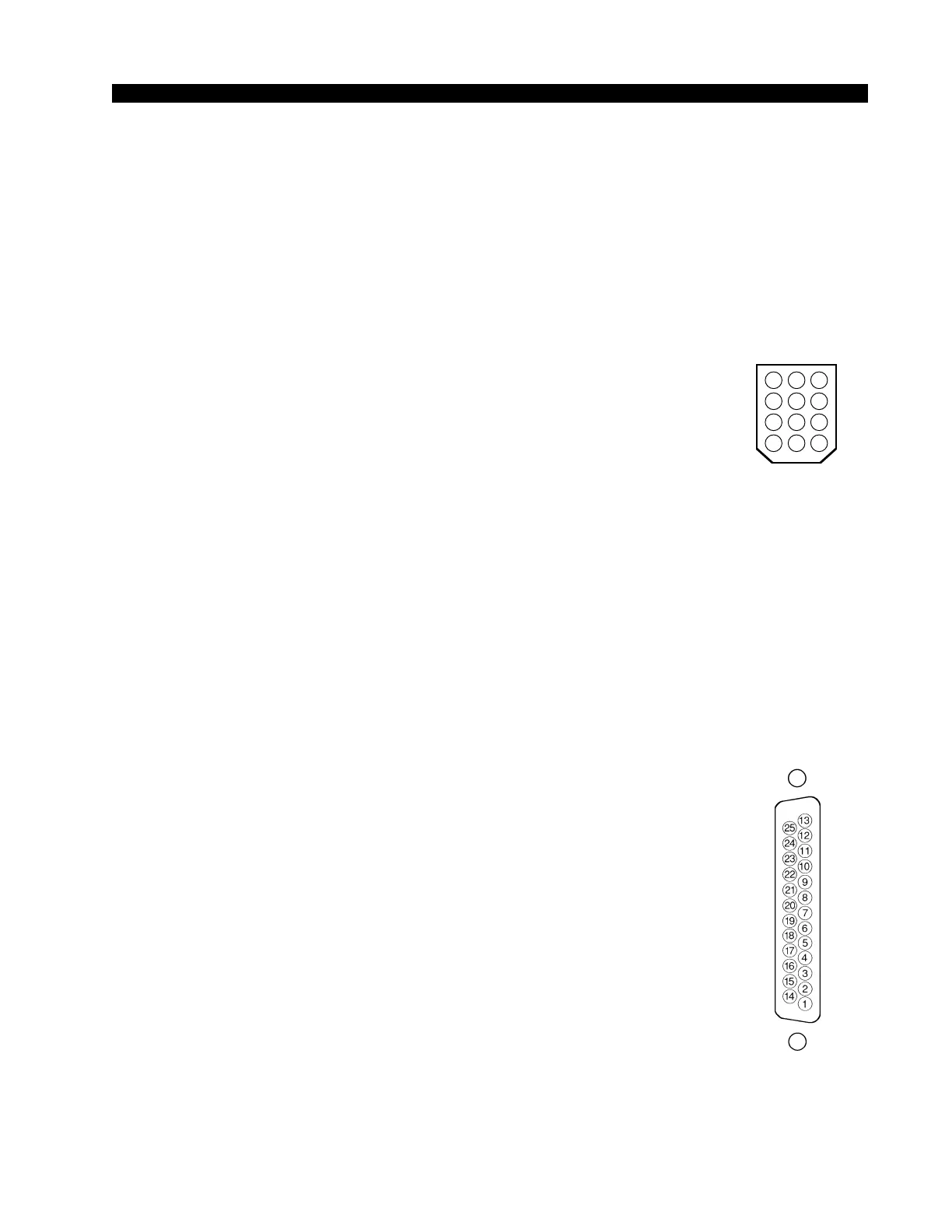
Key diagram showing
back of typical 12-pin I/O
connector plug, with pin
numbers oriented as they
would be seen while wir-
ing. Beveled corners cor-
respond to PCB mounted
mating sockets.
5 46
8 79
11 1012
2 13
Typical DB-25
connector
AMP C connector
AMP D connector