page 5 – 4
RD-12 / March 99
CONTROL ROOM MODULE
Hook-Ups
As stated before, all user wiring to and from the CRD-5 module takes
place at four AMP 12-pin connectors mounted directly beneath the module
on the console mainframe’s bottom pan.
AMP A, B Connectors — Audio
Includes cue, headphone and control room outputs. All audio signals
are +4dBu balanced, analog stereo.
Pin 1 – Lt Cue Out SH
Pin 3 – Lt Cue Out HI
Pin 2 – Lt Cue Out LO
Pin 4 – Rt Cue Out SH
Pin 6 – Rt Cue Out HI AMP A connector
Pin 5 – Rt Cue Out LO
Pin 7 – Lt Hdpn Out SH
Pin 9 – Lt Hdpn Out HI
Pin 8 – Lt Hdpn Out LO
Pin 10 – Rt Hdpn Out SH
Pin 12 – Rt Hdpn Out HI
Pin 11 – Rt Hdpn Out LO
Pin 1 – Lt CR Out SH
Pin 3 – Lt CR Out HI
Pin 2 – Lt CR Out LO AMP B connector
Pin 4 – Rt CR Out SH
Pin 6 – Rt CR Out HI
Pin 5 – Rt CR Out LO
AMP B Connector — Control
The console’s on-air tally port is on the CRD-5 AMP B connector. This
is a simple relay closure that activates whenever programmed input
modules are turned ON (see page 2-4). The port can be used to control an
externally powered tally light that requires a continuous closure to
function.
Pin 11 – On-Air Tally Relay COM
Pin 12 – On-Air Tally Relay N.O.
Maximum current through
the on-air tally relay clo-
sure is 2 amps @30VDC.
!
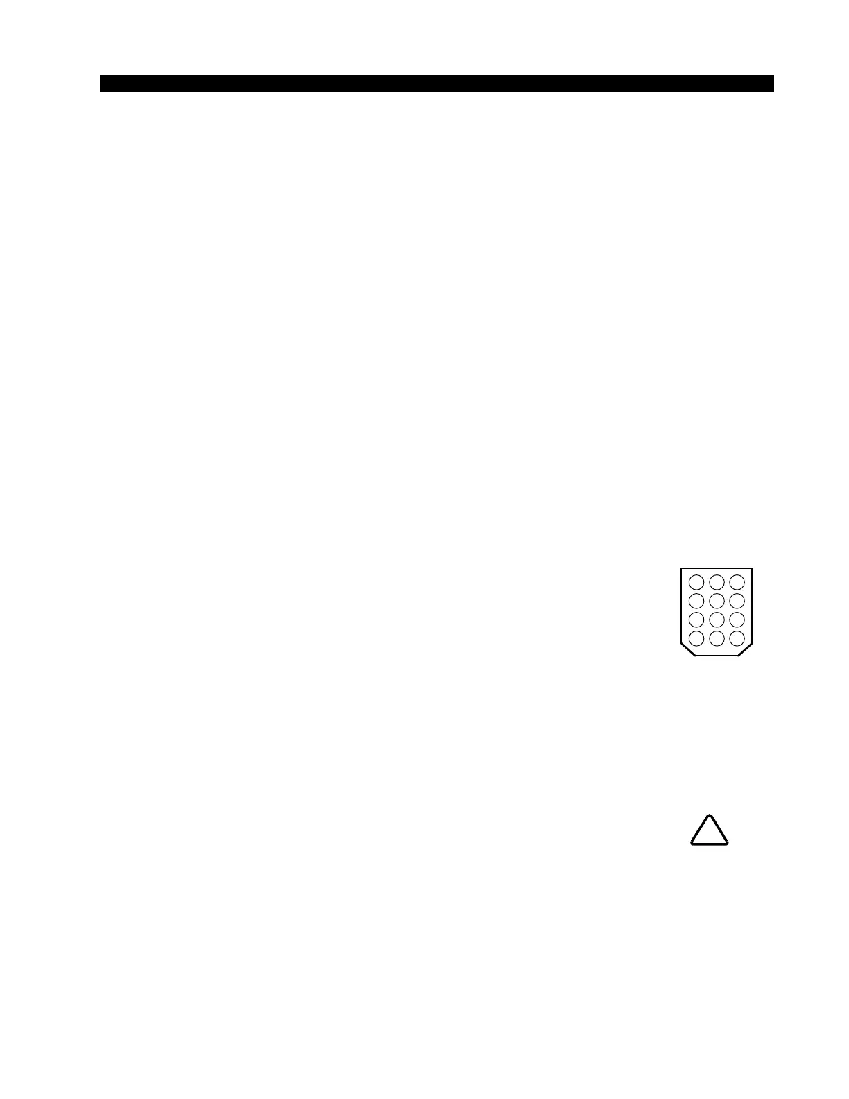
Key diagram showing
back of typical 12-pin I/O
connector plug, with pin
numbers oriented as they
would be seen while wir-
ing. Beveled corners cor-
respond to PCB mounted
mating sockets.
5 46
8 79
11 1012
2 13