page 9 – 6
RD-12 / March 99
SUPERPHONE INPUT
Hook-Ups
As stated before, all user wiring to and from SPD-5 modules takes place
at 12-pin AMP type connectors mounted directly beneath each module on
the console mainframe’s bottom pan.
Audio Connections (AMP A)
These include External In and station Hybrid 1 & 2 inputs. All are +4dBu
balanced analog mono.
Pin 1 – Ext In SH
Pin 3 – Ext In HI
Pin 2 – Ext In LO
Pin 7 – Hybrid 1 In SH
Pin 9 – Hybrid 1 In HI AMP A connector
Pin 8 – Hybrid 1 In LO
Pin 10 – Hybrid 2 In SH
Pin 12 – Hybrid 2 In HI
Pin 11 – Hybrid 2 In LO
Audio and Control Connections (AMP C, D)
These include outputs to the station hybrid, module output composite
feeds (for recording) and remote tape machine START/STOP ports.
Pin 1 – Composite Out SH
Pin 3 – Composite Out HI
Pin 2 – Composite Out LO
Pin 4 – Composite Minus Callers Out SH
Pin 6 – Composite Minus Callers Out HI
Pin 5 – Composite Minus Callers Out LO
Pin 7 – Callers Only Out SH
Pin 9 – Callers Only Out HI AMP C connector
Pin 8 – Callers Only Out LO
Pin 10 – To Hybrid 1 Out SH
Pin 12 – To Hybrid 1 Out HI
Pin 11 – To Hybrid 1 Out LO
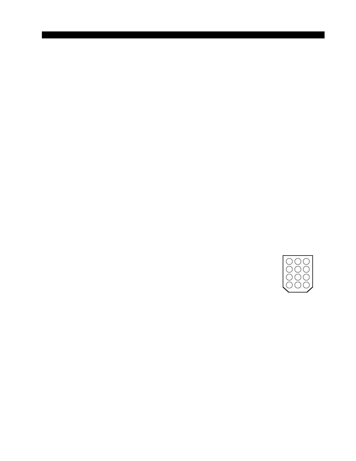
Key diagram showing
back of typical 12-pin I/O
connector plug, with pin
numbers oriented as they
would be seen while wir-
ing. Beveled corners cor-
respond to PCB mounted
mating sockets.
5 46
8 79
11 1012
2 13