List of Figures
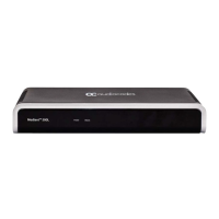
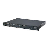
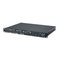
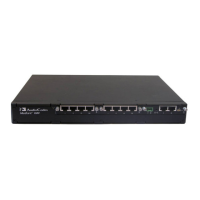
Figure 3-1: Front Panel .......................................................................................................................... 15
Figure 3-2: Rear Panel .......................................................................................................................... 18
Figure 4-1: Location for Applying Rubber Feet ...................................................................................... 19
Figure 4-2: Left Mounting Bracket ......................................................................................................... 21
Figure 4-3: Right Mounting Bracket ....................................................................................................... 21
Figure 4-4: Attaching the Mounting Brackets ........................................................................................ 22
Figure 5-1: Earthing the Device ............................................................................................................. 23
Figure 5-2: Cabling the LAN Ports ......................................................................................................... 24
Figure 5-3: RJ-48c Connector Pinouts for E1/T1 .................................................................................. 25
Figure 5-4: Cabling E1/T1 Port .............................................................................................................. 25
Figure 5-5: RS-232 Cable Adapter ........................................................................................................ 26
Figure 5-6: Cabling Serial Port .............................................................................................................. 26
Figure 5-7: Connecting a USB Storage Device ..................................................................................... 27
Figure 5-8: Connecting to the Power Supply ......................................................................................... 28
 Loading...
