24
8.
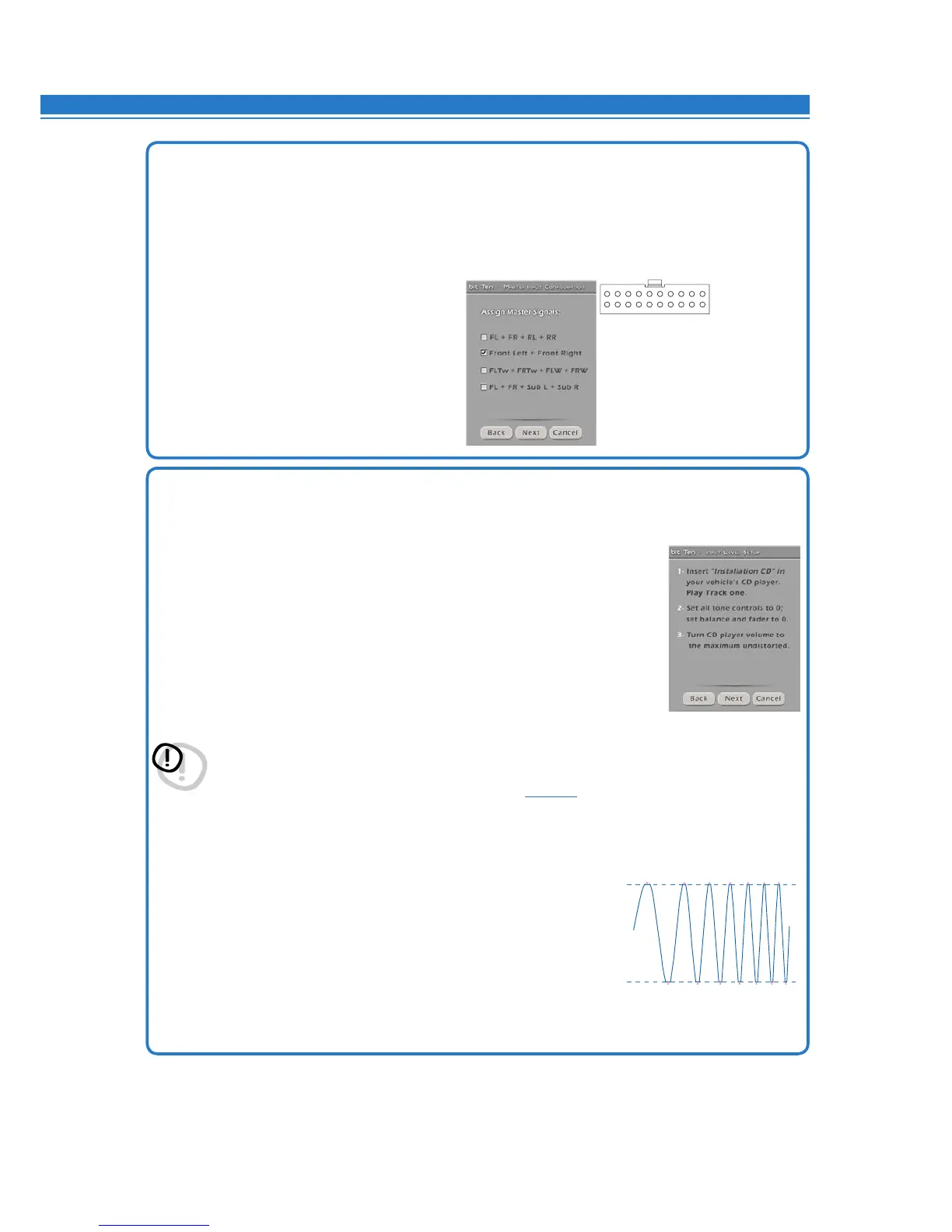
Setting the source.
- Turn on the system and play track 1 of the CD supplied with the bit Ten D.
- Set all tone controls to zero (flat).
- Set balance and fader to center.
- Adjust the head unit volume to the maximum undistorted output level.
- If the source provides an adjustable equalizer, make sure that all controls
are set to zero (flat).
Press BACK to go back to the previous step.
Press NEXT to go ahead with the setup procedure.
Press CANCEL to exit the procedure.
WARNING
the head unit level must be elevated to the maximum undistorted level. If the head unit distortion level
can not be tested in advance, bring the volume to approximately 80% of its maximum. If the head unit
output level is set too low, the device will produce ground noise (hissing sound) when playing music
tracks. This is due to the low signal / noise ratio provided by the bit Ten D input head unit. If you have this
problem, after you calibrate the amplifiers sensitivity
(see 8.1.21)
, increase the head unit volume and
repeat the bit Ten D calibration procedure as detailed in the following chapter 9.
Head unit input-level instrument check.
You will need an oscilloscope for this instrument check.
-
Connecttheheadunitoutputtotheoscilloscope.
-
Playtrack1ofthebit Ten DCD.
-
Settone,faderandbalancecontrolsand
theequalizer(ifany)tozero(flat).
-
Turn on the car.
-
Adjustthevolumecontrolsothattheoscilloscopeshows
a sine wave with slightly cut peaks, as shown in the figure.
-
Notethevolumeusedbytheheadunit.Itmustbeleftinthisposition
for the following operations.
FL ± /FR ± /RL ± /RR ±
IN HI-LEVEL
wires
FL ± (TWL) /FR ± (TWR) /FL ± (WL) /FR ± (WR)
FL ± /FR ± /RL ± (Sub L) /RR ± (Sub R)
FL ± /FR ±
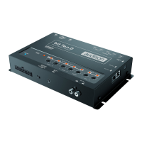
7. How to setup the Master high-level main inputs.
You can assign any processor input channel the identifying name of the signal coming from the source.
The available names are: FL (Front Left Full); FR (Front Right Full); RL (Rear Left Full); RR (Rear Right Full);
FLTW (Front Left Tweeter); FRTW (Front Right Tweeter); FLW (Front Left Woofer); FRW (Front Right Woofer); Sub L
(Sub Left); Sub R (Sub Right).
The bit Ten D will use these names to reconstruct a full range signal coming from an OEM source with a
dedicated multi-channel amplifier and assign the corresponding signal to the respective analog output.
Press BACK to go back to the previous step.
Press NEXT to go ahead with the setup procedure.
Press CANCEL to exit the procedure.
8
CLIP
CLIP