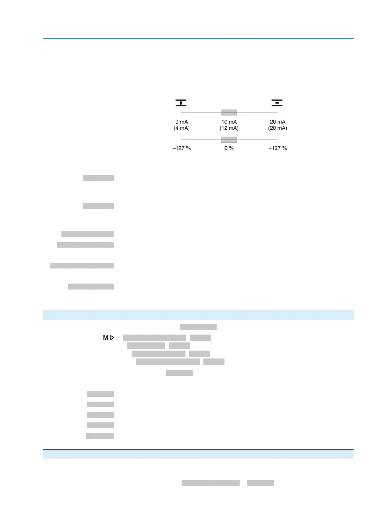
The zero point is in the centre of the selected output range (10 mA or 12 mA). The
torque in direction CLOSE is indicated with 0 – 10 mA or 4 – 12 mA, the torque in
direction OPEN with 10 – 20 mA or 12 – 20 mA. For 127 % of the maximum nominal
output torque, 0 or 4 mA are indicated in direction CLOSE, and 20 mA are indicated
in direction OPEN.
Figure 33: Actual torque value
–127 %= maximum nominal torque in end position CLOSED reached
+127 %= maximum nominal torque in end position OPEN reached
Input AIN 1
Analogue value transmitted via AIN1 (refer to wiring diagram) to the actuator.
Condition: An analogue signal (e.g. 0 – 20 mA) is connected to the analogue input
AIN 1.
Input AIN 2
Analogue value transmitted via AIN 2 (refer to wiring diagram) to the actuator.
Condition: An analogue signal (e.g. 0 – 20 mA) is connected to the analogue input
AIN 2.
Speed target value
Speed setpoint.
Temp. ctrls norm. ‰
Actuator controls temperature (normalised) in per mil.
Condition: MWG position transmitter in actuator.
Temp. ctrl unit norm ‰
Control unit temperature (normalised) in per mil.
Condition: MWG position transmitter in actuator.
Total accel. in %
Total acceleration in percent of oscillation/vibration measurement 0 % = 0.000 g =
0/4 mA; 100 % = 4.000 g = 20 mA
Condition: MWG position transmitter in actuator.
5.3.2. Signal range of analogue output 1
Required user level: Specialist (4) or higher.
Device configuration M0053
I/O interface M0139
Analogue outputs M0335
Signal range AOUT1 M0129
Default value: 0 - 20 mA
Setting values:
0 - 20 mA
Analogue output 1 generates a 0 – 20 mA signal.
4 - 20 mA
Analogue output 1 generates a 4 – 20 mA signal.
20 - 0 mA
Analogue output 1 generates a 20 – 0 mA signal.
20 - 4 mA
Analogue output 1 generates a 20 – 4 mA signal.
X to Y mA
The signal range (X-Y) of the analogue output can be freely configured using two
parameters.
5.3.3. Adjustment of analogue output 1
Initial values and end values of the signal range can be corrected by ± 10 % of the
maximum value range (20 mA)
Example: Parameter Signal range AOUT1 = 4 - 20 mA
The initial value (4 mA) can be adapted within a range of 2 mA to 6 mA.
29
Actuator controls
ACV 01.2/ACVExC 01.2 Signals (output signals)

 Loading...


