3.4 Remote position transmitter For the connection of remote position transmitters (potentiometer, RWG)
screened cables must be used.
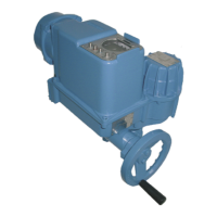
3.5 AUMA MATIC on wall bracket The AUMA MATIC can also be mounted separately from the actuator on a
wall bracket.
.
For the connection of actuator and AUMA MATIC on wall bracket, use suit-
able flexible and screened connecting cables.
(Preconfectioned cables can be obtained from AUMA on request)
.
Permissible cable distance between actuator and AUMA MATIC amounts
to a max. of 100 m.
.
Versions with potentiometer in the actuator are not suitable. Instead of the
potentiometer, an RWG has to be used in the actuator.
.
Connect the wires in correct phase sequence.
Check direction of rotation before switching on.
3.6 Test run P
erform test run. Please refer to the operation instructions pertaining to the
actuator (multi-turn actuator SA(R) ... / part-turn actuator SG ...).
Check limit and torque switching:
Check limit and torque switching, electronic position transmitter RWG or
potentiometer (option) and re-set where appropriate.
The settings are described in the operation instructions pertaining to the
actuator (multi-turn actuator SA(R) ... part-turn actuator SG ... ).
For actuators with feedback signal (RWG, potentiometer), a reference oper-
ation has to be performed after having changed the setting.
Perform reference operation:
.
Run actuator electrically (via the push buttons OPEN and CLOSE of the
local controls) once to the end position OPEN and once to the end posi-
tion CLOSED.
.
If no reference operation is performed after changing the limit switching,
the feedback signal via the bus is not correct. The bus signals the missing
reference operation as warning.
7
Actuator controls AUMA MATIC AM/ AMExB/ AMExC
Short instructions bus connection Profibus DP
Figure B-5: AM on wall bracket
Connecting cable to actuator

 Loading...