AUMA Industry & Marine GmbH
Eichendorffstr. 42 – 48
D-78054 Villingen-Schwenningen
Tel +49 7720 8540-0 · Fax +49 7720 8540-50
info.industry-marine@auma.com · www.haselhofer.de
Die aktuelle Dokumentation ist im Internet verfügbar / Current documentation is available on the Internet
AUMA Industry & Marine GmbH, 08.2018 MON_SBA06-200_DE_EN_rev01.docx / K201-000-310 Seite/page 1/8
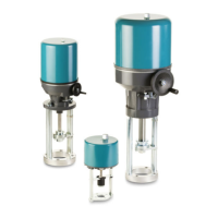
Montageanleitung /
Assembly instruction
SBA 06, SBA 12/20/45,
SBA 80, SBA 200
Anwendungsbereich
Elektrische Schubantriebe betätigen Industriearmaturen mit
linearer Bewegung wie zum Beispiel Stellventile oder
Absperrventile.
Die Antriebe sind nicht als Hebezeuge oder Lastenaufzüge
vorgesehen. Der Einsatz in explosionsgefährdeten
Bereichen oder in strahlenbelasteten Bereichen in
Nuklearanlagen ist nicht vorgesehen.
Range of Application
Electric linear actuators operate industrial valves with linear
movement like control valves or globe valves.
The actuators are not permitted for lifting appliances or as
service lifts. The usage in potentially explosive areas or
radiation exposed areas in nuclear power plants is not
designated.
Inhalt
1.
Sicherheitshinweise ................................... 2
1.1 Grundlegende Sicherheitsanforderungen .. 2
1.2 Erläuterung der Sicherheitssymbole .......... 2
2. Transport, Lagerung, Verpackung ............. 2
3. Technische Beschreibung ......................... 2
3.1 Identifikation .............................................. 2
3.2 Technische Daten ..................................... 2
3.3 Einsatzbedingungen .................................. 2
3.4 Funktionsweise .......................................... 3
3.4.1 Handverstellung ........................................ 3
4. Montage .................................................... 3
4.1 Einbaulage ................................................ 3
4.2 Zusammenbau mit Ventil ........................... 3
5. Elektrischer Anschluss .............................. 3
5.1 Elektrischen Anschluss vornehmen ........... 4
6. Inbetriebnahme ......................................... 4
6.1 Einstellung der Endlagenabschaltung ....... 4
6.2 Probelauf ................................................... 4
6.2.1 Drehrichtungskontrolle .............................. 4
6.2.2 Abschaltung in den Endlagen .................... 4
7. Zertifikat/Certificates .................................. 8
Contents
1. Safety instructions ..................................... 5
1.1 Basic safety requirements ......................... 5
1.2 Explanation of the safety symbols ............. 5
2. Transport, storage and packaging ............. 5
3. Technical description ................................. 5
3.1 Identification .............................................. 5
3.2 Technical data ........................................... 5
3.3 Service conditions ...................................... 5
3.4 Functioning ................................................ 6
3.4.1 Manual operation ....................................... 6
4. Mounting .................................................... 6
4.1 Mounting position ....................................... 6
4.2 Assembly with valve .................................. 6
5. Electric connection ..................................... 6
5.1 Cable connection ....................................... 7
6. Commissioning .......................................... 7
6.1 Setup of the limit switching ........................ 7
6.2 Test run ..................................................... 7
6.2.1 Check direction of rotation ......................... 7
6.2.2 Check limit switching ................................. 7
7. Zertifikat/Certificates .................................. 8