AUMA Industry & Marine GmbH, 08.2018 MON_SBA06-200_DE_EN_rev01.docx Seite/page 6/8
3.4 Functioning
3.4.1 Manual operation
Execute the manual adjustment only with motor being at standstill; hereto
With the left hand press the disengaging rod with plate in direction of the outgoing driving
rod toward the bottom.
Simultaneously turn the handwheel with the right hand until the coupling-in has sensibly
been executed.
To actuate the linear actuator now turn the handwheel; hold the disengaging rod with the
plate in engaged position.
4. Mounting
4.1 Mounting position
The installation position is arbitrary, however not overhead.
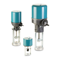
In case of an installation position with horizontally situated driving rod the linear actuator is mounted in a way that both
columns of the yoke are situated in a vertical level one above the other
Figure 4.1-1: Assembly of the actuator with yoke with horizontally situated driving rod
4.2 Assembly with valve
Before making the assembly check whether
the technical data of the linear actuator conform to the conditions of application.
the valve is complete (tie-bar at actuator or valve).
the thread of the valve stem conforms with the threaded bush of the linear actuator.
Move driving rod of the linear actuator into middle position by handwheel.
Remove Coupling parts locking plate [61], anti rotation bar [60] threaded bush [59] by loosening hexagon socket
screws [66]
Lift the actuator over the valve stem and put it onto the bonnet or yoke of valve.
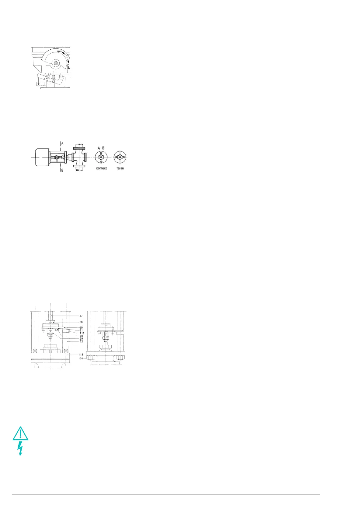
Assemble the coupling according to figure 4.2-1:
Screw counter nut onto the valve stem, Lay the locking plate [61] and anti rotation bar [60] over the valve spindle
and screw threaded bush [59] onto valve stem
Tighten with hexagon socket screws [66]
Tighten actuator with impact nut or fixing screws/fastening nuts
Figure 4.2-1: Coupling / mounting the actuator onto a valve
Please pay attention that no offset occurs between the driving rod of the actuator and the spindle of the valve.
Otherwise this would lead to a loss of performance and premature wear.
Delivery with built-in switching and signalling device and without yoke misc. parts (adjusting lever, slider…) are loosely
attached to the actuator. Assembling is done according to instruction enclosed.
5. Electric connection
Make sure that, appropriate power supplies are utilised assuring that during normal operation or in case of
plant or plant parts failure no dangerous voltages can reach the appliance.
If you do not observe this warning, death, severe body injuries or essential material damages can occur.
For short-circuit protection and for disconnecting the actuator from the mains, fuses and disconnect switches have to
be provided by the customer. The current values for respective sizing can be derived from the current consumption of
the motor (refer to nameplate).
The electrical connection must be carried out exclusively by suitably qualified personnel.
Prior to connection, observe basic information contained in this chapter.