17. Setting the electronic position transmitter RWG (option)
— For remote indication or external control —
After mounting the part-turn actuator to the valve, check setting by
measuring the output current (see sections 17.1 or 17.2) and re-adjust, if
necessary.
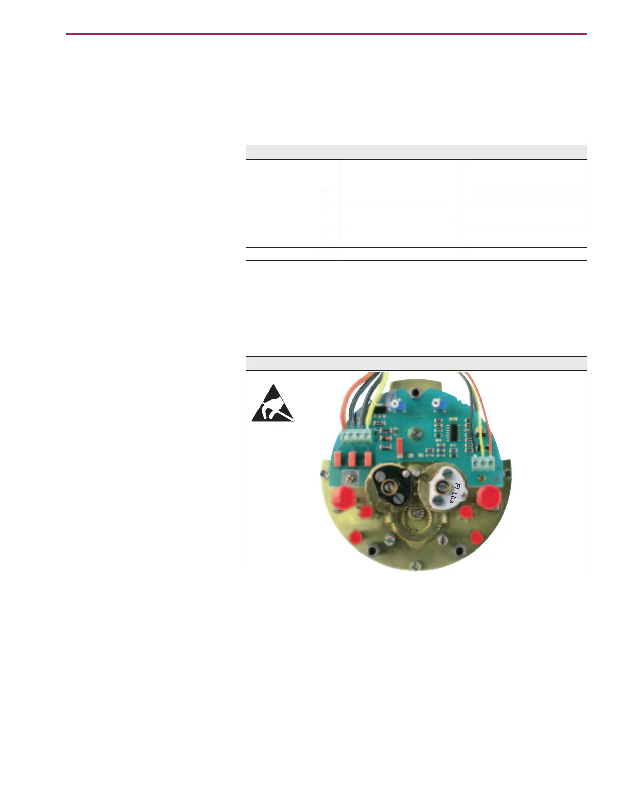
The position transmitter board (figure P-1) is located under the cover plate
(figure P-2).
Part-turn actuators SG 05.1 – SG 12.1 / SGR 05.1 – SGR 12.1
Operation instructions AUMA NORM
Terminal plans
KMS TP_ _ 4 / _ _ _
3- or 4- wire system
KMS TP _ 4 _ / _ _ _
KMS TP _ 5 _ / _ _ _
2-wire system
Output current
I
a
0 – 20 mA, 4 – 20 mA 4 – 20 mA
Power
supply
U
v
24 V DC, ±15 %
regulated
14 V DC + (I x R
B
),
max. 30 V
Max. input
current
I
24 mA at 20 mA
output current
20 mA
Max. load
R
B
600 W (Uv - 14 V) / 20 mA
Table 5: Technical data RWG 4020
Figure P-1: Positioner board

 Loading...


