6. Mounting to valve
.
Prior to mounting, the part-turn actuator must be checked
for any damage. Damaged parts must be replaced by origi
-
nal spare parts.
.
After mounting, check part-turn actuator for damage to
paint finish. If damage to paint-finish has occurred after
mounting, it has to be touched up to avoid corrosion.
.
For butterfly valves, the recommended mounting position is end position
CLOSED (Prior to mounting, bring the part-turn actuator to the mechan
-
ical end stop CLOSED by turning the handwheel clockwise.).
.
For ball valves, the recommended mounting position is end position
OPEN (Prior to mounting, bring the part-turn actuator to the mechanical
end stop OPEN by turning the handwheel counterclockwise.).
.
Thoroughly degrease mounting faces of part-turn actuator and valve.
.
Apply a small quantity of grease to the valve shaft.
.
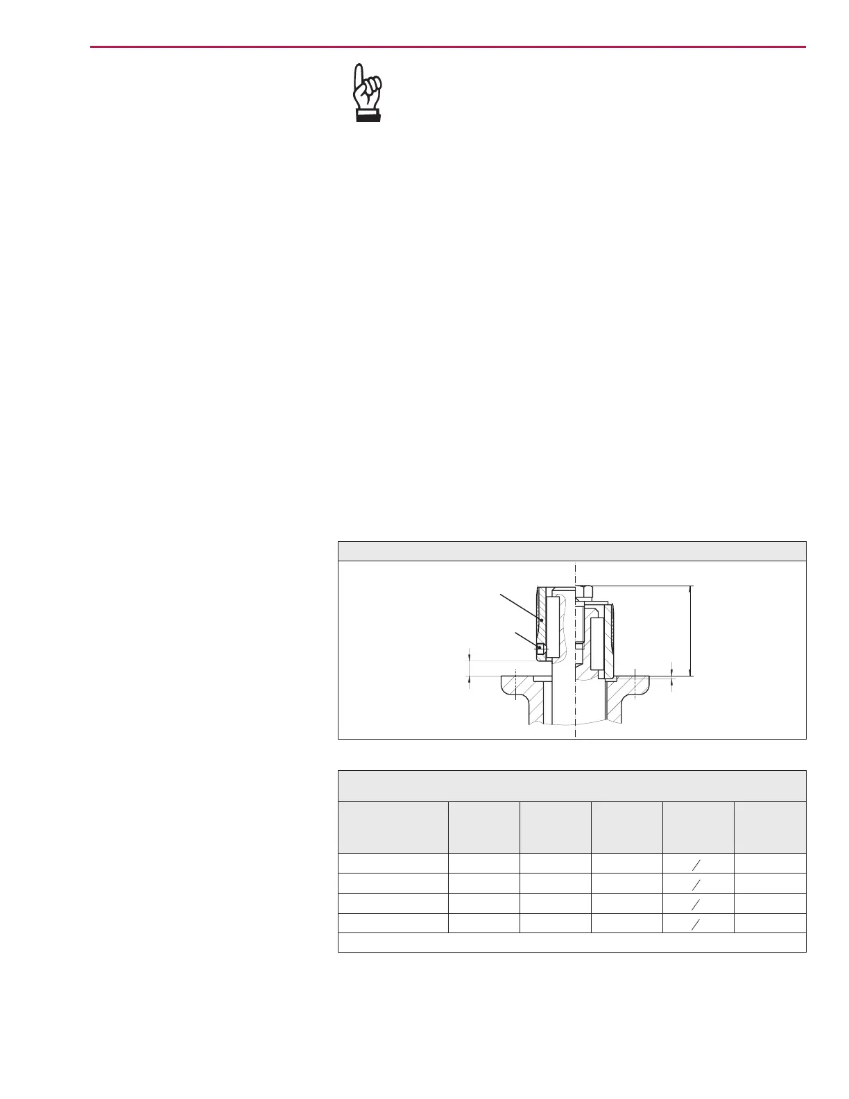
Place coupling sleeve onto valve shaft and secure
(refer to figure B, detail A or B), ensure that dimensions X, Y, and Z are
observed (refer to table 1).
.
Apply non-acidic grease at splines of coupling.
.
Fit actuator so that fixing holes in actuator and valve mounting flange are
in alignment.
If necessary, move actuator up or down one tooth on the coupling. If
required, turn handwheel/crank a little in direction OPEN or CLOSE until
holes align to the threads.
.
Ensure that the spigot (if provided) mates uniformly in the recess and that
the mounting faces are in complete contact.
.
Fasten the actuator with bolts of minimum strength class grade 5 using
lock washers. Fasten bolts evenly crosswise to the appropriate torque
according to table 1.
Part-turn actuators SG 05.1 – SG 12.1 / SGR 05.1 – SGR 12.1
Operation instructions AUMA NORM
A
X
B
Z
Y
Figure B
Coupling
Valve
Set screw
Type
X max. Y max. Z max. Qty. x
threads
(UNC)
T
A
[ft lbs]
SG(R) 05.1-FA07
5 3 60 4 x
5
16
-18 19
SG(R) 07.1-FA07
7 3 60 4 x
5
16
-18 19
SG(R) 10.1-FA12
10 3 77 4 x
1
2
- 13 78
SG(R) 12.1-FA12
10 6 100 4 x
1
2
- 13 78
Conversion factor: 1 Nm corresponds to 1.3529 ft lbs.
Table 1: Dimensions for couplings/fastening torques for bolts

 Loading...


