13. Setting the DUO limit switching (option)
Any application can be switched on or off via the two intermediate position
switches.
For setting, the switching point (intermediate position) must
be approached from the same direction as afterwards in
electrical operation.
13.1 Setting direction CLOSE (black section)
.
Move valve to desired intermediate position.
.
Press down and turn setting spindle G (figure K-2) with a flat blade screw
driver
(5 mm) in direction of arrow, while observing pointer H.
While a ratchet is felt and heard, the pointer H moves 90° every time.
When pointer H is 90° from mark C, continue turning slowly.
When pointer H has reached the mark C, stop turning and release setting
spindle. If you override the tripping point inadvertently (ratchet is heard
after the pointer has snapped), continue turning the setting spindle in the
same direction and repeat setting process.
13.2 Setting direction OPEN
(white section)
.
Move valve to desired intermediate position.
.
Press down and turn setting spindle K (figure K-2) with a flat blade screw
driver in direction of arrow, while observing pointer L.
While a ratchet is felt and heard, the pointer L moves 90° every time.
When pointer L is 90° from mark F, continue turning slowly.
When pointer L has reached the mark F, stop turning and release setting
spindle. If you override the tripping point inadvertently (ratchet is heard
after the pointer has snapped), continue turning the setting spindle in the
same direction and repeat setting process.
13.3 Checking the DUO
limit switches
The red test buttons T and P (figure K-1) are used for manual operation of the
DUO limit switches.
.
Turning T in direction of the arrow TSC (DSR) triggers DUO limit switch CLOSED.
The torque switch CLOSED is actuated at the same time.
.
Turning P in direction of the arrow TSO (DOEL) triggers DUO limit switch OPEN.
The torque switch OPEN is actuated at the same time.
Part-turn actuators SG 05.1 – SG 12.1 / SGR 05.1 – SGR 12.1
Operation instructions AUMA NORM
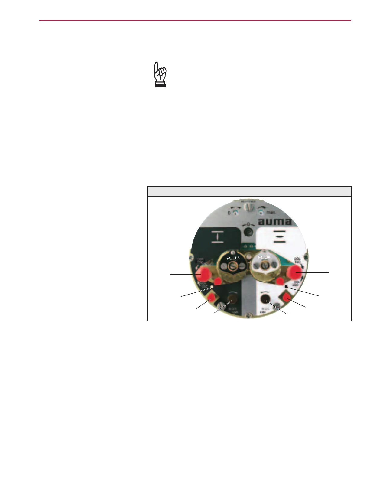
Figure K-2: Control unit
G
T
H
C
K
P
L
F

 Loading...


