14. Setting the torque switching
14.1 Setting
.
The set torque must suit the valve!
.
This setting must only be changed with the consent of the
valve manufacturer!
.
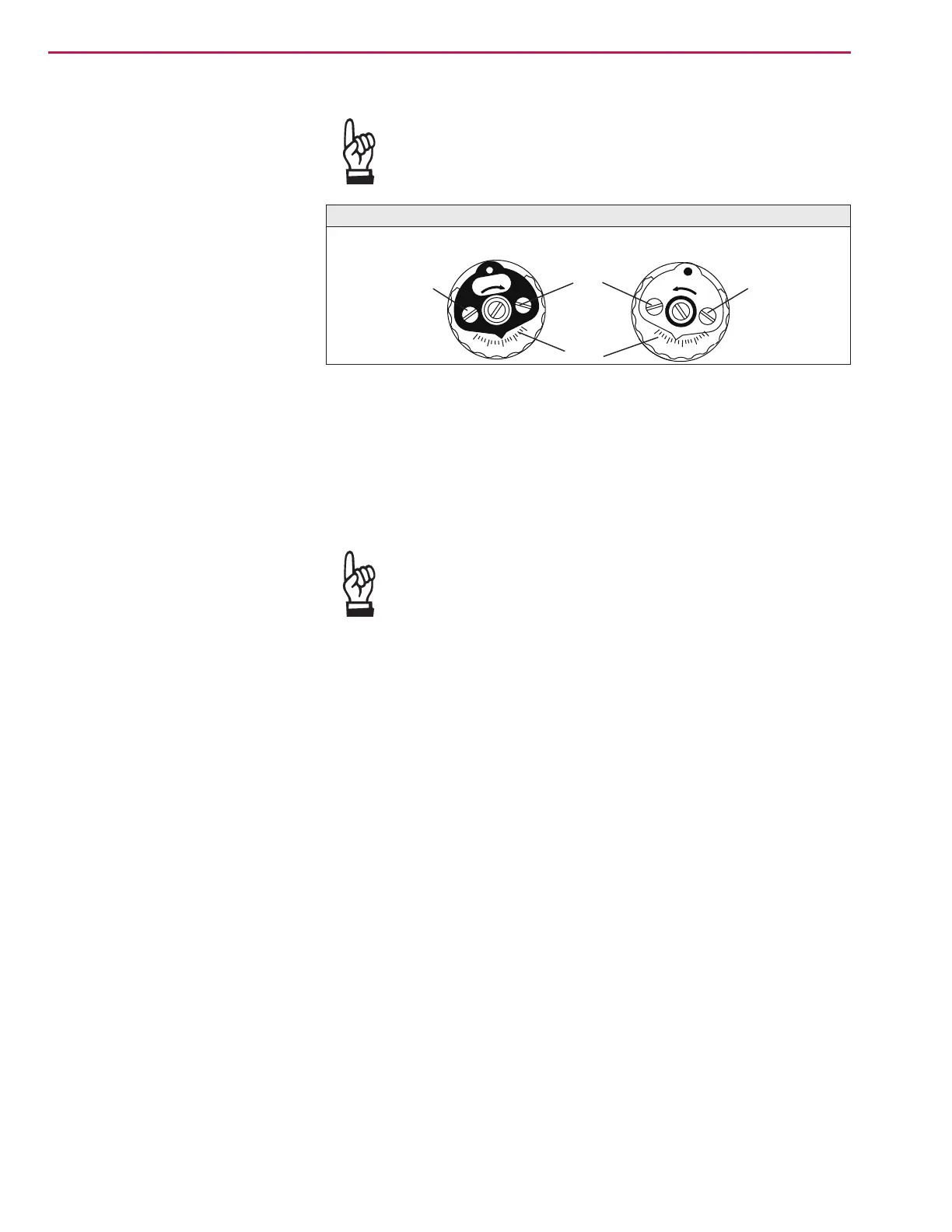
Loosen both lock screws O at the torque dial (figure L).
.
Turn torque dial P to set it to the required torque (1 da Nm = 10 Nm).
Example:
Figure L shows the following setting:
90 ft lbs. for direction CLOSE
95 ft lbs. for direction OPEN
.
Tighten lock screws O again
.
The torque switches can also be operated in manual
operation.
.
The torque switching acts as overload protection over full
travel, also when stopping in the end positions by limit
switching.
14.2 Checking the torque switches The red test buttons T and P (figure K-1) are used for manual operation of
the torque switches:
.
Turning T in direction of the arrow TSC (DSR) triggers torque switch
CLOSED.
.
Turning P in direction of the arrow TSO (DOEL) triggers torque switch
OPEN.
.
If a DUO limit switching (optional) is installed in the actuator, the interme
-
diate position switches will be operated at the same time.
Part-turn actuators SG 05.1 – SG 12.1 / SGR 05.1 – SGR 12.1
AUMA NORM Operation instructions
Ft. Lbs
Ft. Lbs
70
80
100
110
90
110
100
80
70
90
Figure L: Torque switching heads
Setting CLOSED
Setting OPEN
O
O
P
O

 Loading...


