EasyManua.ls Logo

Autel OTOFIX D1 User Manual

Autel OTOFIX D1
3 pages
To Next Page IconTo Next Page
Page #1 background imageLoading...
Page #1 background image
Thank you for purchasing OTOFIX diagnostic tool. This tool is manufactured to a high standard and will provide years of trouble-free
performance when used in accordance to these instructions and properly maintained.
Quick Reference Guide
Functional Description
OTOFIX V1
OTOFIX D1/OTOFIX D1 Lite
Powered by
Web: www.otofixtech.com
1
2 3
4
1. 7-inch Touchscreen
2. Built-in Microphone
3. Power LED
4. Ambient Light Sensor
5. Speaker
6. Camera
7. Camera Flash
8. USB OTG/Charging Port
9. USB Port
10. Micro SD Card Slot
11. Power/Lock Button
5
6 7
11
1
4
5
2
3
1. Flashlight Power Button
2. Power LED
3. Vehicle/Connection LED
4. Vehicle Data Connector (16-pin)
5. USB Port
OTOFIX V1 Description
LED
Power LED
Vehicle/
Connection LED
Color Description
Yellow
Green
Green
Flashing Red
Blue
VCI is powered on and performing self-check.
VCI is ready for use.
Firmware is updating.
• Solid Green: VCI is connected via USB cable.
• Flashing Green: VCI is communicating via USB cable.
• Solid Blue: VCI is connected via Bluetooth.
• Flashing Blue: VCI is communicating via Bluetooth.
8
9 10
Question and Answer IconNeed help?

Do you have a question about the Autel OTOFIX D1 and is the answer not in the manual?

Autel OTOFIX D1 Specifications

General IconGeneral
Operating SystemAndroid
RAM2GB
ConnectivityWi-Fi, Bluetooth
Display7-inch touchscreen
ProcessorQuad-core
ProtocolsOBDII, CAN, J1939, ISO9141
Diagnostic Functionslive data
LanguagesMultiple languages

Summary

OTOFIX Diagnostic Tool Functional Description

Diagnostic Tablet Components

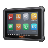
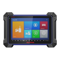
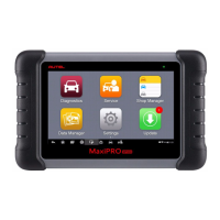
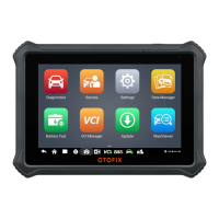
Identifies key parts of the diagnostic tablet, including touchscreen and ports.

VCI (Vehicle Communication Interface) Components

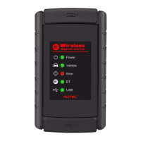
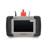
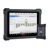
Details the OTOFIX V1 unit's physical components and connections.

OTOFIX V1 Unit Details

V1 LED Indicators and Connection States

Explains the color codes for V1 power and vehicle/connection status LEDs.

OTOFIX Quick Start Guide

Connect V1 to Vehicle OBDII Port

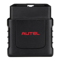
Instructions for inserting the V1 into the vehicle's OBDII port for connectivity.

Power On Diagnostic Tablet

Steps to power up the diagnostic tablet for initial use.

Establish V1 and Tablet Communication

Guide to pairing the diagnostic tablet with the V1 via Bluetooth.

Confirm VCI Connection for Diagnosis

How to check the VCI status icon on the tablet to ensure readiness.

Related product manuals