Do you have a question about the Auto Mate AM6.2 and is the answer not in the manual?
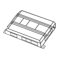
Lists the main control module and included accessories like transmitters and switches.
Details how to identify and connect to a constant 12V wire for power.
Provides steps to locate the vehicle's starter wire using a multimeter.
Explains how to find the +12V switched ignition wire for system operation.
Guides on locating the accessory wire for climate control and other features.
Instructions for finding and testing the positive parking light wire for flashing signals.
Method for identifying the tachometer wire using AC voltage measurement.
Procedure for finding the wait-to-start bulb wire in diesel vehicles.
Details the pinout and function of the 9-pin primary harness.
Outlines the pinout and function of the 4-pin satellite harness.
Explains the wiring for the heavy gauge relay interface for high current circuits.
Details the 3-pin connector for door lock control functions.
Describes the pinout and function of the 5-pin remote start harness.
Wire function for disarming the factory alarm system.
Wire function for rearming the factory alarm system.
Ignition output for interfacing with RF systems or other security modules.
Input for activating or deactivating the remote start system.
Provides a 200mA negative output for status indication or bypass activation.
Outputs for activating additional accessories or secondary starters via relays.
Connects to high current 12V sources for powering relays and high-draw circuits.
Connects to the vehicle's ignition wire to control the ignition circuit.
Connects to the vehicle's accessory wire for climate control and other features.
Connects to the vehicle's starter wire to engage the starter motor.
Prevents remote start activation in gear by connecting to the neutral safety switch.
Receives engine RPM signal for tachometer learning and monitoring.
Shuts down remote start if the brake pedal is depressed.
Disables remote start if the vehicle hood is opened.
Output for defogger activation or status indication.
Instructions for bypassing Passlock I and II systems using specific bypass modules.
Information on bypassing Passkey III and other transponder-based immobilizers.
Jumper setting to determine positive or negative polarity for light flash output.
Jumper to adjust tachometer signal sensitivity for various vehicles.
Describes the function and connection of the program switch.
Step-by-step guide to teach transmitters to the system's receiver.
Explains engine monitoring methods and settings.
Configurable options for engine run duration and parking light behavior.
Settings for starter crank duration and voltage monitoring sensitivity.
Configuration for activation pulses and secondary ignition/accessory outputs.
Settings for diesel timer input and door lock pulse durations.
Options for single or double pulse outputs for door lock/unlock functions.
Features for ignition-controlled locks and factory alarm disarming.