Do you have a question about the Auto Mate 553 and is the answer not in the manual?
Important pre-installation checks and advice for a successful setup.
Post-installation checks and testing procedures to ensure proper functionality.
Guidance on optimal placement for the siren to ensure security and prevent tampering.
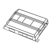
Recommendations for mounting the control module securely and away from heat sources.
Instructions on locating reliable constant 12V power sources in the vehicle.
Wiring guide for Type A door lock systems using positive 12V pulses.
Jumper setting to adjust tach signal threshold for specific vehicles.
Jumper setting to configure positive or negative light flash output.
How to program transmitters for standard button assignments.
How to program transmitters for single button arm/disarm operation.
Overview of basic system features and their default settings.
Overview of advanced system features and their programmable options.
Details on programming remote start related features.
Common alarm issues and their solutions.