20 9
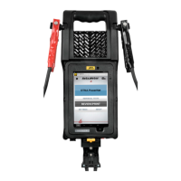
• Power Button: To power on, push and hold the button for 1 second, then
release.
• To put the unit “to sleep”, push and hold the power button for about 2
seconds.Theword“Sleep”willashonceonthescreen,thenyoucanletgo
of the button, and the screen will go dark. When in sleep mode, the power
buttonwillashgreenabouteverythreeseconds.
• To “wake up” the tester from “Sleep” mode, simply push the power button for
about 1 second, then let go.
• To power the unit off, push & hold the power button for 5 or 6 seconds. The
word“Off”willashonceonthescreen,thenyoucanletgoofthebutton.
• Printer Compartment: Lift up on the tab in the center of the printer
compartment door to open the door, and to access the paper roll. To close,
simply push it shut at both lower corners until it clicks shut.
• Settings: This displays the tester Model Number, Serial Number, Firmware
Date, Date & Time, Store number, Store address, Store phone number,
Temperature units, Language, and Wi-Fi SSID.
• Flash Light:Amomentarytouchoftheashlighticononthescreenwillturn
ontheashlightonthebackoftheunit.Anothermomentarytouchofthisicon
willturntheashlightoff.
• Full System Test: This is used for a complete test which includes Battery,
Starting System, and Charging System. See page 14 for further information
on performing a Full System Test.
• Battery Test: This is used for a battery-only test in, or out of the vehicle. See
page 11 for further information on performing a Battery Test.
• Review Results: This unit stores up to 1,000 test results, and you can
review past results by touching this icon. See page 18 for further information
on reviewing results.
• Infrared Thermometer: Aim the thermometer on the back of the tester, at the
battery to be tested.
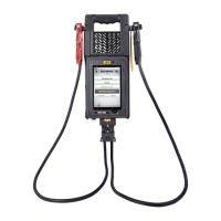
MAINTENANCE
Bothjawsofeachclampmustrmlyengagethebatteryterminal.Onecopperjaw
contains a wire that reads the voltage and the other jaw connects to another wire
that draws the load in each test. Damaged clamps or loose wires will affect the
readings. Keep clamps clean and in good repair.
Over time the battery clamps will need to be replaced if any of the following are
indicated:
• If there is excessive damage or corrosion to the cables or clamps.
• If there are signs of frayed, or broken wires between the tester and the
clamps.
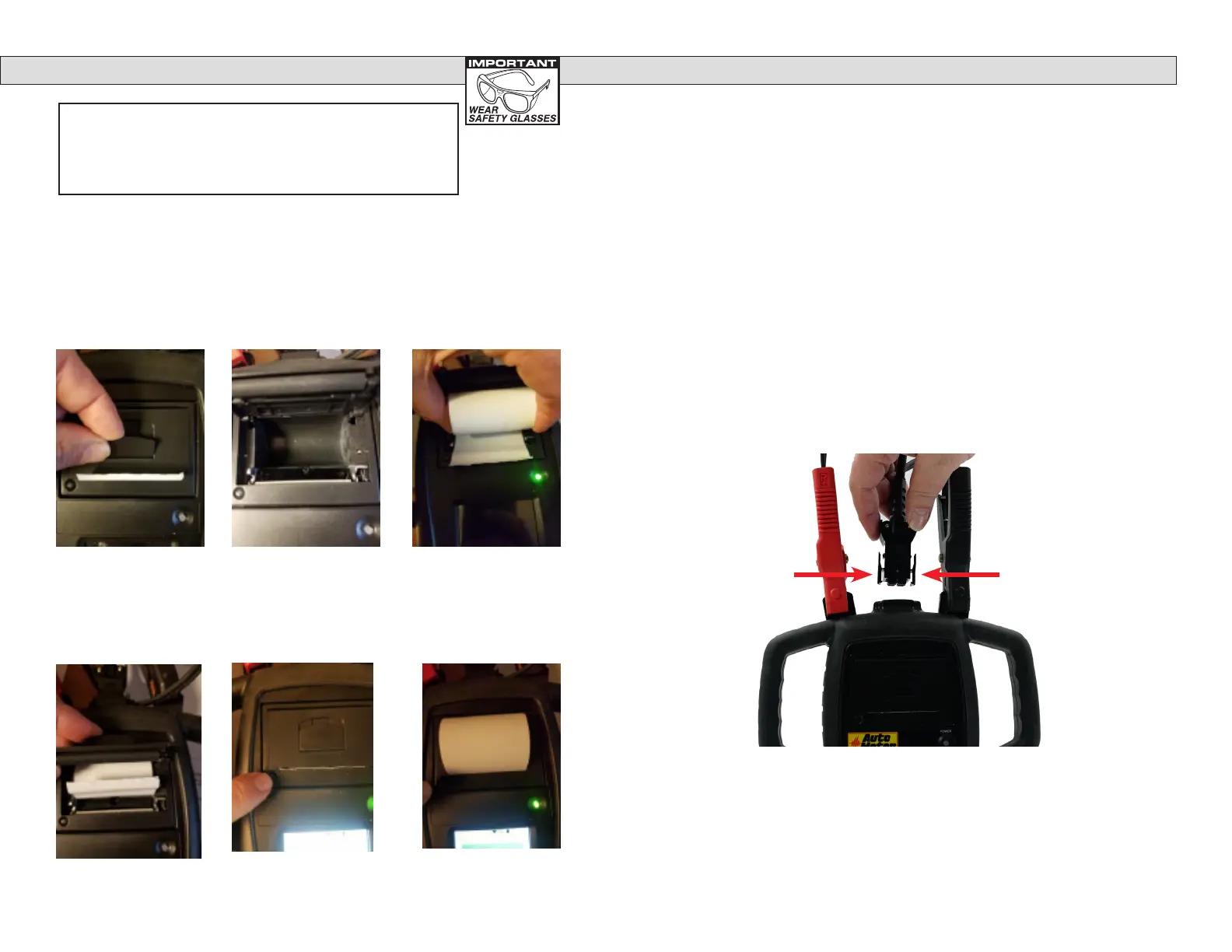
• Grasp the leads connector at the top of the tester, and squeeze the two
locking tabs toward each other, and then pull the connector out of the
tester.
• The clamps & leads are offered as a complete set.
• To install, simply plug the connector of the new set into the top of the
tester until the locking tabs click, and are seated. The connector will only
plug in, one direction with the black connectors on top and the red
connectors on the bottom.
This tester is rechargeable and should be stored on the optional charging dock or
plugged into the wall outlet charger when not in use. When the tester is charging,
thepowerbuttonwillashred.Whenthetesterisnishedcharging,thepower
buttonwillashgreen.
BATTERY CLAMP/LEAD REPLACEMENT
PROCEDURE
Order Auto Meter model number AC-124 Replacement Lead Set
Charging the Tester
PRINTER (BVA-360P VERSION)
To Access the Printer
Paper, lift up on the
tab as shown in the
picture below, and
pull the printer door
open.
Printer Status Light:
If the Paper Feed Button/Status Light blinks twice quickly, then
the paper has run out, or the paper is not correctly inserted
underneath the printer door. A single, occasional blink means
the printer is functioning correctly.
Push the lid closed,
with the end of the
paper sticking out of
the tester.
You can push the button at the lower left of the
printer door to manually feed paper. The tester
must be on for the paper feed to function. If the
tester is in “Sleep” mode or turned off, it will not
feed paper when you push the button.
Clear out any old
paper, or debris from
the printer cavity.
Simply drop in the
new paper, with the
end of the paper
coming out from un-
derneath the roll, and
closest to the screen.
As shown.
 Loading...