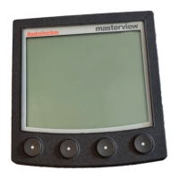
EasyManuals Logo

AUTOHELM ST4000+ Service Manual

AUTOHELM ST4000+
34 pages
To Next Page IconTo Next Page
To Previous Page IconTo Previous Page
Page #6 background imageLoading...
Page #6 background image
ST4000+ Autopilots
2 ST4000+ Autopilots Service Manual 83115-1
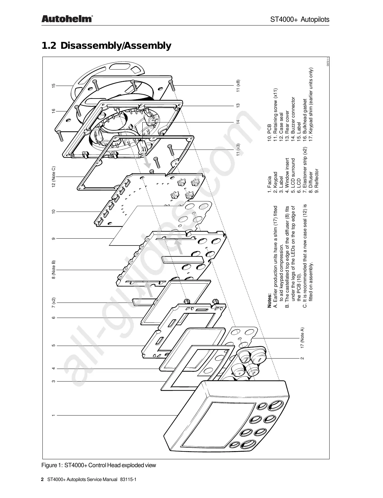
1.2 Disassembly/Assembly
1. Facia
2. Keypad
3. Label
4. Window insert
5. LCD surround
6. LCD
7. Elastomer strip (x2)
8. Diffuser
9. Reflector
D3721-1
2 17 (Note A)
1345
6 7 (x2) 8 (Note B) 9 10 12 (Note C)
11 (x3) 14 13 11 (x8)
10. PCB
11. Retaining screw (x11)
12. Case seal
13. Rear cover
14. Buzzer connector
15. Label
16. Bulkhead gasket
17. Keypad shim (earlier units only)
Notes:
A. Earlier production units have a shim (17) fitted
to aid keypad compression.
B. The castellated top edge of the diffuser (8) fits
under the legs of the LEDs on the top edge of
the PCB (10).
C. It is recommended that a new case seal (12) is
fitted on assembly.
15
16
Figure 1: ST4000+ Control Head exploded view
All manuals and user guides at all-guides.com
all-guides.com

Other manuals for AUTOHELM ST4000+

Questions and Answers:

Question and Answer IconNeed help?

Do you have a question about the AUTOHELM ST4000+ and is the answer not in the manual?

AUTOHELM ST4000+ Specifications

General IconGeneral
TypeAutopilot
Drive TypeWheel Drive
Control UnitST4000+ Control Head
Power Supply12 V DC
InterfaceSeaTalk
Display TypeLCD
ControlPush-button
Voltage12 V
CompassFluxgate Compass
Course Accuracy±1°
Compass Safe Distance1 meter

Related product manuals