ST4000+ Autopilots
4 ST4000+ Autopilots Service Manual 83115-1
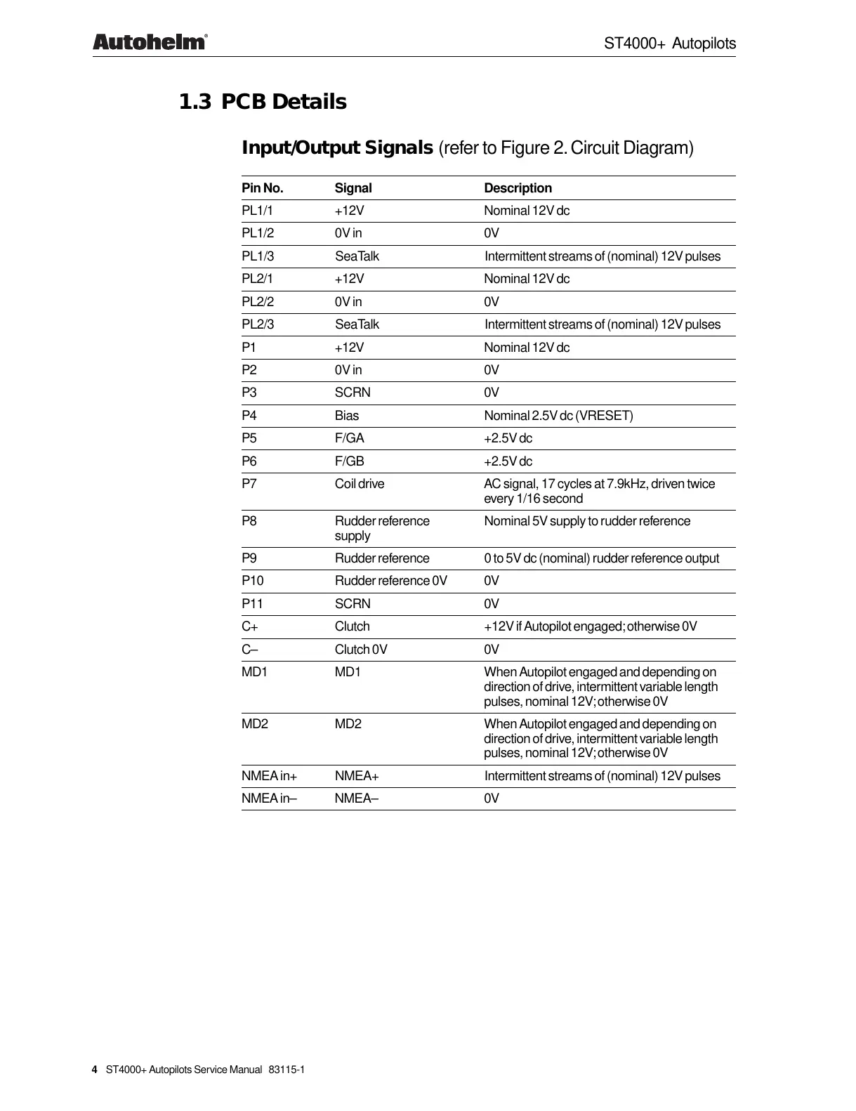
1.3 PCB Details
Input/Output Signals (refer to Figure 2. Circuit Diagram)
Pin No. Signal Description
PL1/1 +12V Nominal 12V dc
PL1/2 0V in 0V
PL1/3 SeaTalk Intermittent streams of (nominal) 12V pulses
PL2/1 +12V Nominal 12V dc
PL2/2 0V in 0V
PL2/3 SeaTalk Intermittent streams of (nominal) 12V pulses
P1 +12V Nominal 12V dc
P2 0V in 0V
P3 SCRN 0V
P4 Bias Nominal 2.5V dc (VRESET)
P5 F/GA +2.5V dc
P6 F/GB +2.5V dc
P7 Coil drive AC signal, 17 cycles at 7.9kHz, driven twice
every 1/16 second
P8 Rudder reference Nominal 5V supply to rudder reference
supply
P9 Rudder reference 0 to 5V dc (nominal) rudder reference output
P10 Rudder reference 0V 0V
P11 SCRN 0V
C+ Clutch +12V if Autopilot engaged; otherwise 0V
C– Clutch 0V 0V
MD1 MD1 When Autopilot engaged and depending on
direction of drive, intermittent variable length
pulses, nominal 12V; otherwise 0V
MD2 MD2 When Autopilot engaged and depending on
direction of drive, intermittent variable length
pulses, nominal 12V; otherwise 0V
NMEA in+ NMEA+ Intermittent streams of (nominal) 12V pulses
NMEA in– NMEA– 0V