ST50 PLUS RADAR Operation and Installation Handbook
_-------------------_
DISPLAY UNIT
;
I
HV
-SV
E
VD
E
E
TUGS
TUNVIPW
TUNI/SHM
+lZV/BP
+DC
-DC
+NMEA
-NMEA
,______--_--________------
------I
I
, ANTENNA UNIT
I
I
1
1
I
1
#
I
I
T ELK
I
8
I
I
01
E
I
I
I
t
@
2
VD-R
8
I
1
COAX.
4
8
w
03
VD
,
I
I
I
I
I
I
a
4 DC-R
i
I
1
I
I
I
~-~~-~~~~_-~~~~~_-~~--_----J
+
TO SHIP’S POWER
I
I
5: LARGE WIRE
------------------J
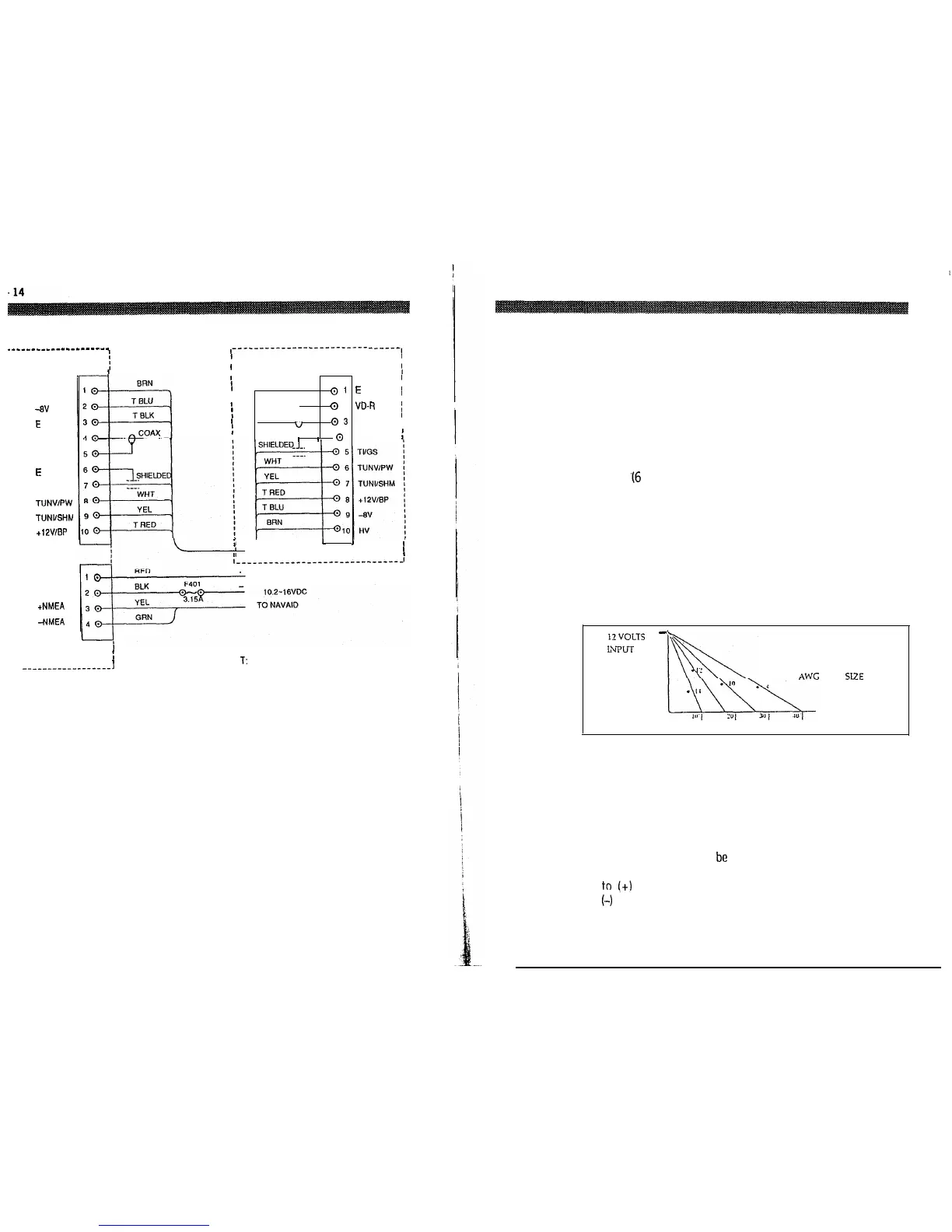
Fig. 2-11 Radar Interconnection Diagram
Section 2. Installation
2.4 Electrical Connections
2.4.1 DC Power Connection
The ST50 is intended for use on DC ships power systems and can
operate as long as that DC supply system is maintained from 10.2 to
16 Vdc. The DC system can be “negative” grounded or have both
positive and negative supply lines “floating” above ground. This radar
is not intended for use on “positive” ground vessels.
A 2 m
.I6
ft.) power cable assembly is furnished for connecting the
ship’s DC power into the radar. Longer power cable runs may require
that larger wire sizes be used to minimize anyvoltagedrop in the cable.
In order to properly determine the supply cable wiring size to use if the
power cable must be extended, a graph is supplied in TABLE 2-l for
recommending an appropriate cable diameter. Begin by estimating
the length of cable you will require between the ship’s main power
source and the radar. Select the wire size indicated by the distance
and input voltage.
12VOLTS
-
LLPIJT
VOLTAGE
AWG
WIRE SIZE
POWER CABLE LENGTH
Table 2-1 Power Cable Size Versus Length
Table 2-1 is a recommended guide for selecting power cable wire
sizes based on the length of the cable to the ships’ power connection
point.
The connections should be made at a power distribution panel,
isolation switch, or may
be
made (but not preferred) to the battery.
Check that all connections are clean. The RED wire must be connected
to !+I positive battery terminal and the BLACK wire to
(-1
negative battery terminal. The shielded wire should be connected
to the ships RF ground.