ST50 PLUS RADAR Operation and
installation
Handbook
-
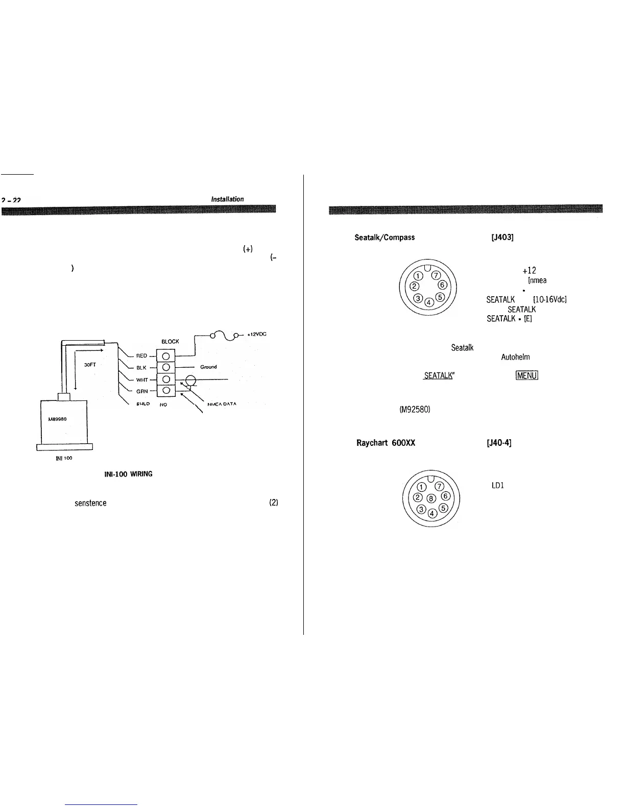
When connecting power to the sensor OBSERVE PROPER POLARITY!
The RED wire should be connected to the POSITIVE (+I source
terminal; the BLACK wire should be connected to the NEGATIVE
f-
)
source terminal. If the power leads are reversed the sensor will not
operate.
It it appears that the sensor is inoperative, check the input voltage
polarity with a DVM or VOM and if necessary, reverse the wires to
correct the error.
h
TERMINAL BLOCK
I
\
DATA COMMON
Ml39980
L4
INt
100
Fig. 2-16
INI-
WRING
Notes: The sensor is designed to output the NMEA 0183 “HDM”
senstence for the radar. The sensor can supply data for up to two (2)
external inputs which conform to the NMEA interface requirements.
Ensure that the wiring is as shown in Fig. 2-16, above.
To avoid ground loops DO NOT CONNECT the sensor cable shield to
ground.
Section 2. Installation
2-23
2.4.2.5
Seatalk/Compass
Interface Connection
[J403]
*solder side shown
1 COMPASS E
2 COMPASS +12
3 COMPASS + fnmea data1
4 COMPASS
-
[data common1
5 SEATALK Vcc UO-16Vdcl
6 TX-RX
SEATALK
DATA
7 SEATALK
-
[El
In order to view Seatalk data on the bottom of the ST50 display, a
simple connection to your existing Autohelm capable equipment is all
that is required. Once connected, you simply need to select “DISPLAY
RADAR
SEATALK”
by held depressing
ml
key or from the MAIN
menu in order to see the split screen capabilities of the ST50.
An external compass sensor such as a Smart Heading Sensor
(M92580) can also be connected to the ST50 display unit as shown
above.
2.4.2.6
Raychart
600Xx
Interface Connector [J40-41
‘solder side shown
1
E
2
LDO
3
LDl
4 LD2
5 LD3
6
LOAD
7 FRAME
8 LCD CLK