ST50 PLUS RADAR Operation and Installation Handbook
A 5 meter cliff has a radar horizon of 5 nm. Therefore, under standard
conditions, the cliff should begin to appear on the screen when the ship
comes within 5.0 + 5.0 = 10 nm.
3.3 Operating Controls
Generally the operation of the ST50 is easy and straight forward.
However, the navigator who takes the time to become fully familiar with
the panel layout and understands the functions of the various controls
will be able to obtain the best performance from his equipment.
3.3.1 Layout of the Controls
The layout of controls is shown in Figure 3-2.
3.3.2 Functions of the Controls
r-iJ
‘POWER’ STBY/XMlT KEY
In the “OFF” state no power is applied to the radar system. Upon
Pressing the STBY/XMIT key, ship’s DC power is applied to the
scanner and display units. The radar normally requires
approximately 90 seconds to warm up. A countdown timer on the
radar display shows the time remaining in the warm up period.
During the warm-up period the radar transmitter does not operate
and antenna does not rotate.
After the warm up period, one beep will sound and “PUSH
XMIT
TO OPERATE” will be displayed on the screen.
The display will also show the operating time (hours) of the radar
during the warm up period, as well as the software level
(i.e.
vl .O).
The radar is now available for operation.
Pressing the STBY/XMIT key puts the radar into the “transmit’
mode. The antenna will begin rotation, and targets will be
displayed on the screen.
If the
STBY/XMIT
key is pressed again, the radar will return to the
“stand-by” condition with the transmitter OFF and the “PUSH XMIT
TO OPERATE” indication again appears on the screen.
Section 3. Operation
By pressing and holding down the STBY/XMIT key indication
approximately 2 seconds, the radar will be turned OFF and all
alphanumeric information on-screen will extinguish.
@-I
RANGE KEY
By pressing the UP (Right side) or DOWN (Left side) of the key, the
desired range scale can be selected.
Each time the radar is turned on, the initial range displayed will be
the same range scale that was previously in use when the radar
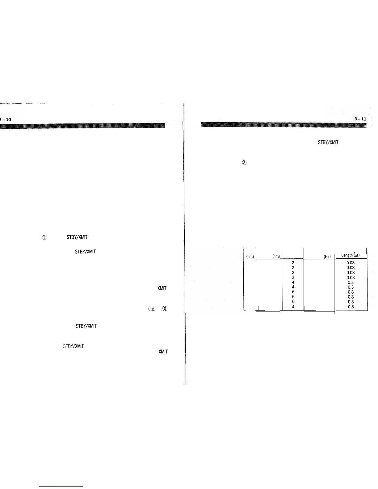
was turned off. During range changes, the UP and DOWN keys
change not only the range scaling, but simultaneously change the
number and interval of the fixed range rings as well as the pulse
repetition frequency and the pulse length for the radar transmitter.
Table 3-1 shows this relationship.
Table 3-l Relation of Range, Rings and Pulse Length
Range
trim)
0.125
0.25
0.5
0.75
1.0
1.5
3
6
12
16
0.0625
0.125
0.25
0.25
0.25
0.25
0.5
2
4
Range Ring Number of Pulse Repetition Transmitting Pulse
1
Interval
trim) Rings
Frequency (Hz)
2250
2250
2250
2250
1200
1200
600
600
600
600
The small dot on this key indicates a decrease in selection, while the
larger dot represents an increase.