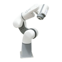
M8 Connector Pin Colour PIN Function
1 Brown Eb_24V
2 White Eb -E- Stop Channel A
3 Blue Ea -E-Stop Channel B
4 Black Ea _24V
This port is not in use, and is reserved for future expansion.
Download the latest software, along with the latest version of this manual from
https://automata.tech.
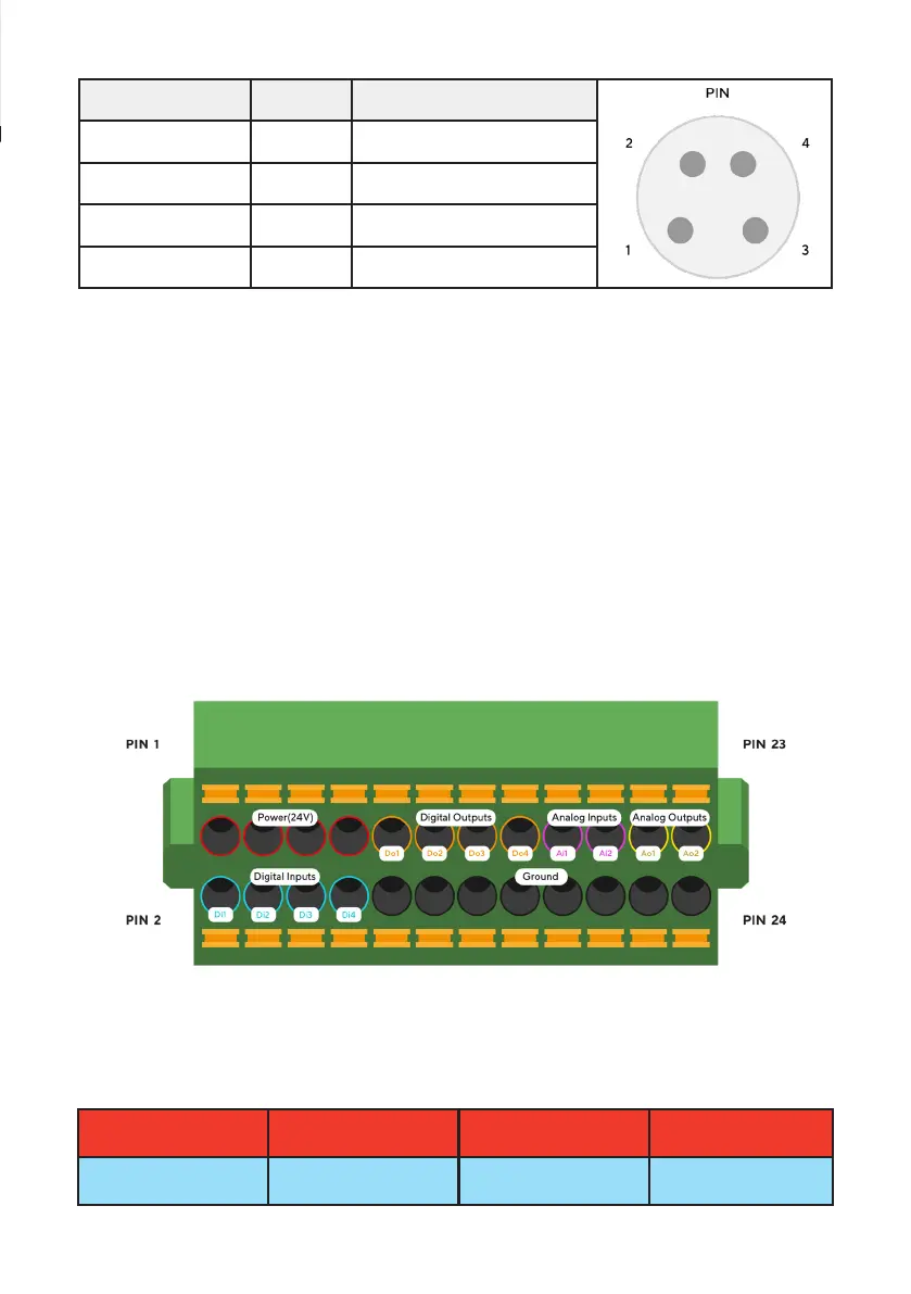
The connector pins are spring terminated. Press and hold the orange tab to
retract the spring and insert a stripped wire end, then release the orange tab to
engage the spring and lock the wire in place. The connector is designed for use
with 16 - 24 AWG wire.
A) Power
There are four 24 V power pins on the base I/O, which can collectively source
a maximum of 1.875 A. These are found in the first four columns of the top row:
2. Reserved Stop Connection
3. Base I/O
24 V (Pin 1)
Base Di1 (Pin 2)
24 V (Pin 3)
Base Di1 (Pin 4)
24 V (Pin 5)
Base Di1 (Pin 6)
24 V (Pin 7)
Base Di1 (Pin 8)
19