OptiFlex™ I/O Expanders (part no. FIO)
Automated Logic Proprietary and Confidential A Carrier Company. © 2022 Carrier.
All rights reserved.
11
Screw Mount
Leave about 2 in. (5 cm) on each side of the controller for wiring.
Insert #6 screws through the mounting tabs. Use no more than 8 in.lbs. torque to secure plastic tab to
mounting surface.
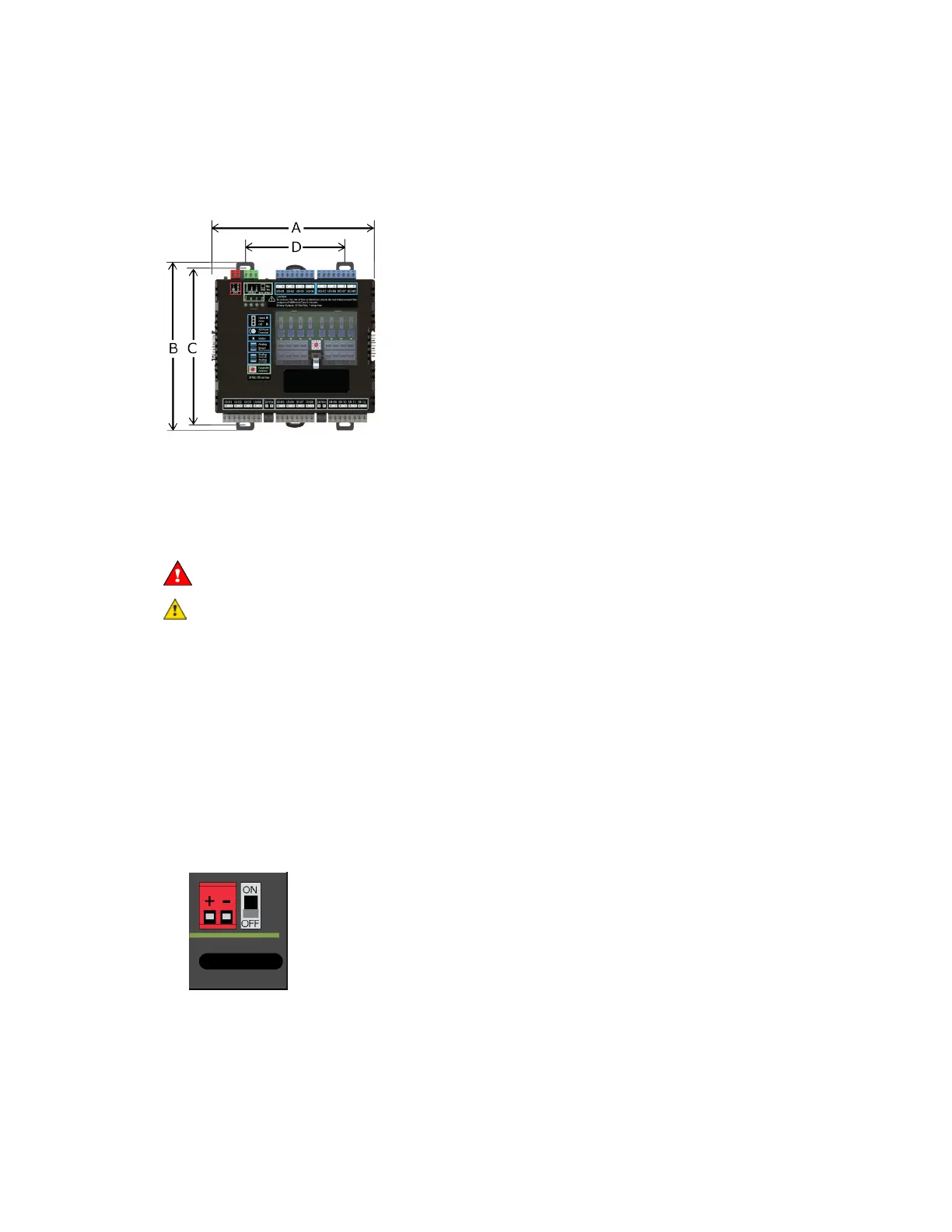
A:
B:
C:
D:
Depth:
6.9 in. (17.53 cm)
6.95 in. (17.65 cm)
6.45 in. (16.38 cm)
4.1 in. (10.4 cm)
2.24 in (5.69 cm)
To wire an external power supply to the expander
When wiring the expander to the controller's I/O Bus port, you need an external power supply for the
expander. See FIO expander power and communication configurations (page
6).
WARNING Do not apply line voltage (mains voltage) to the controller's ports and terminals.
CAUTIONS
• The FIO expander is powered by a Class 2 power source. Take appropriate isolation measures
when mounting it in a control panel where non-Class 2 circuits are present.
• Automated Logic® controllers can share a power supply as long as you:
○ Maintain the same polarity.
○ Use the power supply only for Automated Logic® controllers.
To wire the power supply to the expander
1 Make sure the FIO expander’s power switch is in the OFF (down) position to prevent it from
powering up before you can verify the correct voltage.
2 Remove power from the power supply.
3 Pull the red screw terminal connector from the expander's power terminals labeled 24 V (+/-).
4 Connect the power supply's wires to the red screw terminal connector.
 Loading...