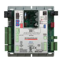
ZN551 Control Module
Technical Instructions
What is the ZN551 control module? ........................................................................... 2
Module driver and control program ................................................................2
Specifications ...............................................................................................2
Inputs ...........................................................................................................3
Room sensors................................................................................................3
Digital outputs...............................................................................................3
Analog outputs..............................................................................................3
To mount the ZN551.................................................................................................. 4
Wiring for power ........................................................................................................ 4
To wire for power............................................................................................4
To address the ZN551................................................................................................ 5
Wiring for communications ........................................................................................ 5
Wiring specifications .....................................................................................5
To wire the ZN551 for communications ..........................................................5
Wiring inputs and outputs .......................................................................................... 6
Wiring specifications .....................................................................................6
To wire inputs and outputs ............................................................................. 7
Downloading memory................................................................................................ 9
To download memory in WebCTRL..................................................................9
To assign inputs or outputs to points........................................................................... 9
Input values.................................................................................................10
Output values..............................................................................................10
Resolution values ........................................................................................11
Offset/Polarity values..................................................................................11
Using flow sensors................................................................................................... 12
To connect the duct tubes to the flow sensors...............................................12
To wire the flow sensor to the control module................................................12
To set up the Airflow Control microblock.......................................................12
To set up the module driver ...................................................................................... 13
Driver ..........................................................................................................13
Device.........................................................................................................14
Notification Class #1...................................................................................14
Common Alarms..........................................................................................15
Custom Translation Tables...........................................................................15
To communicate through the local access port .......................................................... 16
To set up a Local Access connection in WebCTRL..........................................16
Troubleshooting ...................................................................................................... 16
Formatting the control module.....................................................................17
LED's..........................................................................................................17
Manufacture date........................................................................................18
Compliance ............................................................................................................ 18
Automated Logic Corporation • 1150 Roberts Blvd. • Kennesaw, GA 30144 • 770/429-3000 • Fax 770/429-3001 •
www.automatedlogic.com • © 2005 Automated Logic Corporation. All rights reserved throughout the world. Automated
Logic Corporation, the Automated Logic logo, WebCTRL, EIKON, BACview, SuperVision, and InterOp are registered
trademarks, and Alert is a trademark of Automated Logic Corporation. BACnet
®
is a registered trademark of ASHRAE.
All other brand and product names are trademarked by their respective companies.