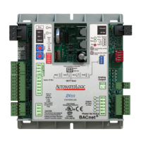
3 In the Num field for each point, type the number of the control module's
corresponding input or output. For example, if you use DO1 on the
ZN551 for the point Fan S/S, type 1 in the Num field for Fan S/S.
NOTE Exp (expander number) is 0 for the ZN551.
4 Enter the appropriate values for each input and output in the remaining
columns. See Input values, Output values, Resolution values and
Offset/Polarity values below.
NOTE You can also enter these values in EIKON for WebCTRL.
5 If you have not performed the initial memory download to the ZN551, you
must download now so you can verify inputs and outputs.
6 To verify each input's operation, force each sensor to a known value, then
compare it to the Value shown on the control program's Point Checkout
tool in WebCTRL.
7 To verify each output's operation, lock each output to a known condition
on the control program's Point Checkout tool in WebCTRL, then verify
that the equipment operates correctly.
Input I/O Type Sensor/Actuator Type Min/Max
Analog (BAI)
0–5 Vdc 0–5 Volt Linear Full Range
Engineering values
associated with 0 Vdc (Min)
and 5 Vdc (Max)
1
Thermistor Thermistor
Select your Thermistor
type or set up and select
a Non-Linear, Custom
Table
2
N/A
Digital (Binary) (BBI)
Dry Contact Dry Contact N/A N/A
Input values
1
The sensor reads a value and sends a corresponding signal (Volt, mA, or psi) to the
ZN551's physical input. The Analog Input microblock uses the Min and Max values to
linearly translate the signal into the engineering value used in subsequent control logic.
For example, set Min to 0 and Max to 10 for a 4–20 mA sensor that measures velocity
from 0.0 to 10.0 inches/second so that when the input reads 4 mA, the microblock
outputs a value of 0. Similarly, when the input reads 8 mA, the microblock outputs a
value of 2.5.
2
To set up a custom translation table, see the module driver's Custom Translation Tables
properties page in WebCTRL.
Output I/O Type Sensor/Actuator Type Min/Max
Analog (BAO)
0–10 Vdc
Electrical
0–10 Volt
Linear Full Range
Engineering values
associated with 0 Vdc (Min)
and 10 Vdc (Max)
1
2–10 Vdc
Electrical
0–10 Volt
Linear w/Offset,
2–10 Volts
Engineering values
associated with 2 Vdc (Min)
and 10 Vdc (Max)
1
Output values
ZN551 Control Module • Rev. 3/17/2005 10 © 2005 Automated Logic Corporation

 Loading...