measured from its input to ground and must share the same ground as the
control module.
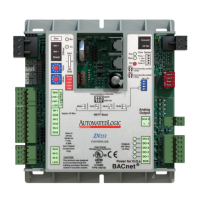
To mount the ZN551
Screw the ZN551 into an enclosed panel using the mounting slots provided
on the cover plate. Leave about 2 in. (5 cm) on each side of the control
module for wiring.
Mounting slo
Mounting slo
Wiring for power
CAUTIONS
• The ZN551 is a Class 2 device (less than 30 Vac, 100 VA). Take
appropriate isolation measures when mounting it in a control panel
where non-Class 2 devices (120 Vac or greater) are present.
• Do not power pilot relays from the same transformer that powers the
ZN551.
NOTE You can power several control modules from the same transformer if
you maintain the same polarity.
To wire for power
1 Remove power from the 24 Vac transformer.
2 Pull the screw terminal connector from the control module's power
terminals labeled Gnd and 24 Vac.
3 Connect the transformer wires to the screw terminal connector.
4 Apply power to the transformer.
5 Measure the voltage at the ZN551’s power input terminals to verify that
the voltage is within the operating range of 21.6–26.4 Vac.
6 Insert the screw terminal connector into the ZN551's power terminals.
7 Verify that the Power LED is on and the Run LED is blinking.
ZN551 Control Module • Rev. 3/17/2005 4 © 2005 Automated Logic Corporation

 Loading...