To wire inputs and
outputs
1 Verify that the ZN551's power and communications connections work
properly.
2 Pull the screw terminal connector from the control module's power
terminals labeled Gnd and 24 Vac.
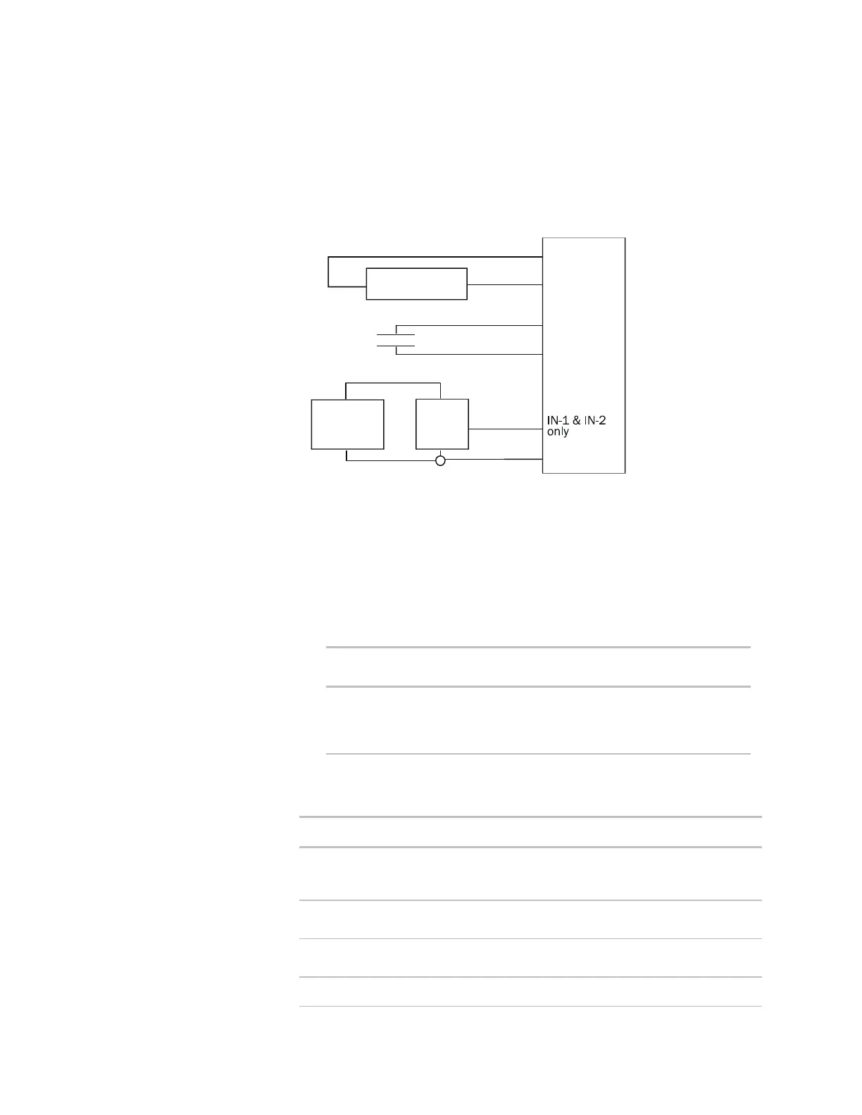
3 Connect the input wiring to the screw terminals on the ZN551.
NOTE Connect the shield wire to the GND terminal with the ground
wire.
thermistor
Relay,
dry contact
+V
Gnd
Out
Any input
Any input
Gnd
Gnd
Gnd
DC
power
supply
0-5Vdc
+V
Gnd
4 To wire a room sensor to the ZN551, wire the ZN551's terminals to the
room sensor's terminals.
○ For an RS room sensor, wire each terminal on the ZN551's Rnet port
to the terminal of the same name on the RS room sensor.
NOTE If wiring an RS room sensor with shielded wire, connect the
shield wire to the GND terminal with the ground wire.
○ For a LogiStat room sensor, use the following table.
Wire this terminal
on the LStat port...
To this terminal on
the LogiStat sensor
Gnd
IN-4
IN-5
LED
Gnd
Temp
SW
LS5v
5 Set the appropriate jumpers on the ZN551.
To use... For...
IN-1 or IN-2 Thermistor
Dry contact
0–5 Vdc
Set jumpers IN-1 or IN-2 to the type of signal the
input will receive.
IN-4 or IN-5 Thermistor
Dry contact
Verify the LStat/IN-4 jumper is on.
IN-4 and IN-5 LogiStat 1. Remove the jumper from LStat/IN-4.
2. Set the LStat/Rnet jumper to LStat.
Rnet Port RS sensor Set the LStat/Rnet jumper to Rnet.
ZN551 Control Module • Rev. 3/17/2005 7 © 2005 Automated Logic Corporation
 Loading...