Thermistor/dry contact
0-5Vdc
Thermistor/dry contact
0-5Vdc
IN-2
IN-1
Rnet
LStat
LStat
IN-4
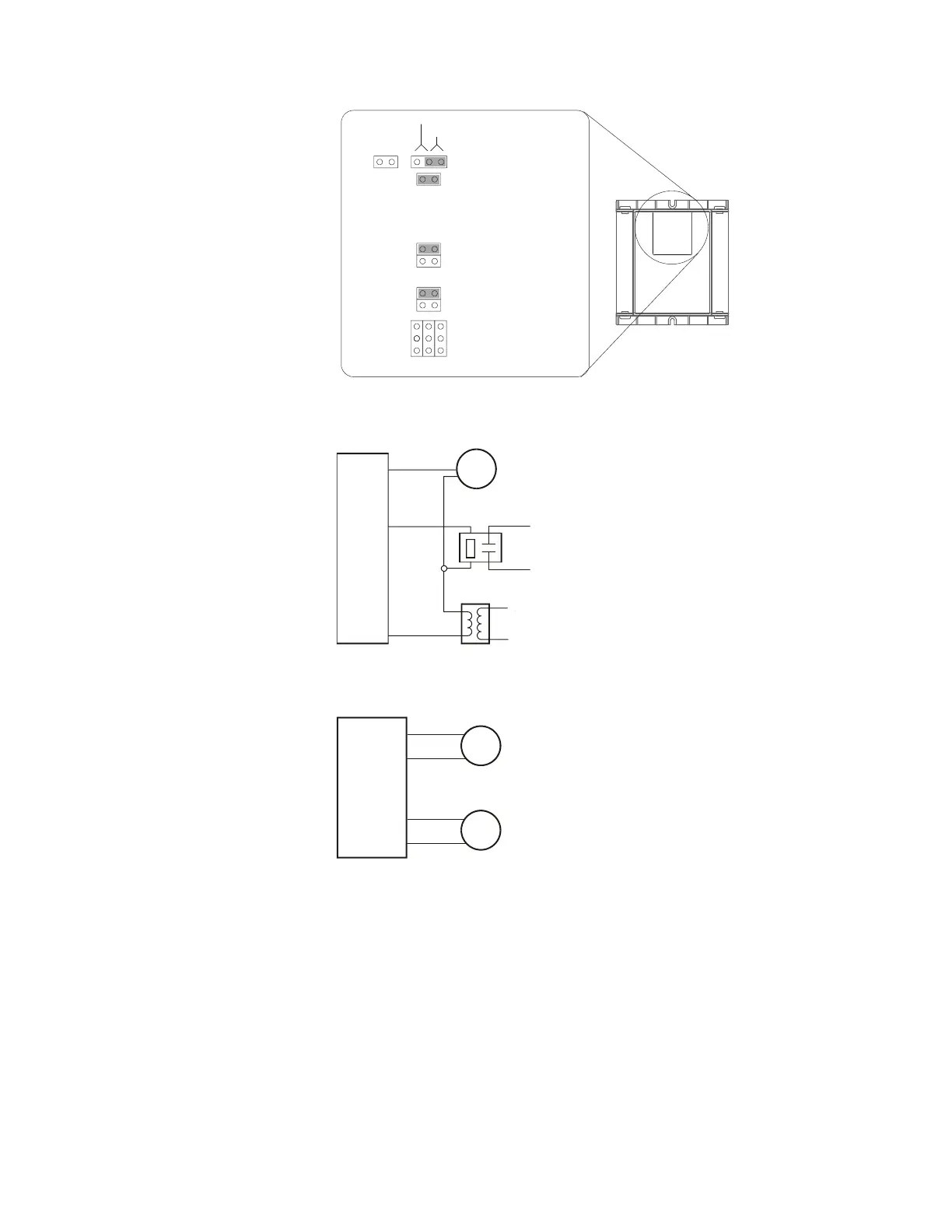
6 Connect the digital output wiring to the screw terminals on the ZN551
and to the controlled device.
24 Vac or
24 Vdc
Motor
Any DO
Any DO
Bus
7 Connect the analog output wiring to the screw terminals on the ZN551
and to the controlled device.
+
Gnd
0-10 V
0-10 V
Motor
Valve
Any AO
+
Gnd
Any AO
NOTE Current from the analog outputs can drive a 20 mA device. To use
an analog output for this purpose, you may need to add a 1/2 watt
resistor in series with the device to achieve the required total resistance
of 500 Ohms. For example, to drive a device that has 100 Ohms of
resistance, wire a 400 Ohm resistor in series with the 20 mA device to
achieve 500 Ohms resistance.
8 Insert the power screw terminal connector into the ZN551's power
terminals.
ZN551 Control Module • Rev. 3/17/2005 8 © 2005 Automated Logic Corporation
 Loading...