4
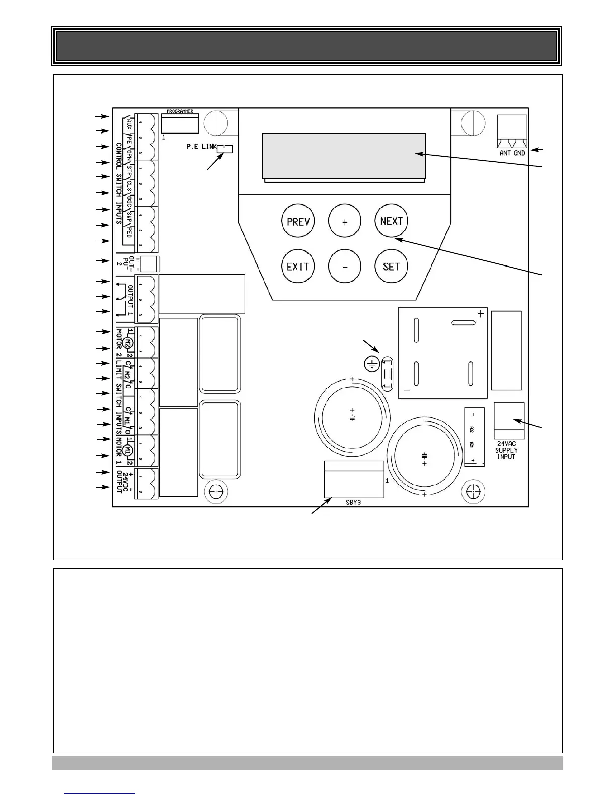
CONTROL BOARD LAYOUT
1 Aux control input
2 P.E N/C input terminal (remove 25 when used)
3 OPN N/O input terminal
4 STP N/O input terminal
5 CLS N/O input terminal
6 OSC N/O input terminal
7 SWP N/O input terminal
8 PED N/O input terminal
9 COM terminal for input terminals 1 to 8
10 OUTPUT 2 (optional relay module coil drive
output)
11 OUTPUT 1 N/C relay contact
12 OUTPUT 1 COM relay contact
13 OUTPUT 1 N/O relay contact
14 MOTOR 2 terminal 1
15 MOTOR 2 terminal 2
16 MOTOR 2 close limit switch input terminal
17 MOTOR 2 open limit switch input terminal
18 COM terminal for Terminals 16,17,19 & 20.
19 MOTOR 1 close limit switch input terminal
20 MOTOR 1 open limit switch input terminal
21 MOTOR 1 terminal 1
22 MOTOR 1 terminal 2
23&24 24VDC output for powering accessories
25 PE input jumper (remove when 2 is used)
26 Standby battery / solar charger connector
27 Mains Earth connection
28 24VAC power input (from transformer)
29 Console keypad
30 Console display (LCD)
31 Antenna connector
AA..TT..AA
CCBB1199
FFiirrmmwwaarree
##..####
1
2
3
4
5
6
7
8
9
10
11
12
13
14
15
16
17
18
19
20
21
22
23
24
26
28
27
31
29
30
25
Com