Owner Installation Instructions GDO-11v1 SecuraLift
®
25
Step 20 - Fitting the P.E. Beams (optional)
Affi x the P.E. Beams in a strategic location within
the doorway. We recommend 150mm above the
fl oor level and as close as possible to the door
opening, inside the garage.
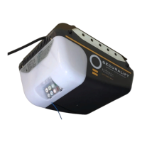
Connect the wires from the P.E.Beams wiring
harness to terminal block (Fig. 46). The wiring
diagram is for Model PE-2 (Order Code 90214).
Make sure that you are using the correct resistor
i.e. 2k2 ohms (Red Red Red gold) and connecting
to number 2 (two) and 4 (four) terminal on the PE-2
receiver. Make sure to align the beams correctly.
Follow the manual supplied with the P.E. Beams.
WARNING: When using P.E. Beams, the doorway
must be clear of all obstructions and persons at all
times. The location of the beams and manner in
which it is installed might not give safety protection
at all times. Check to make sure that the height of
the beam and type used give maximum protection
possible.
WARNING: Install the P.E.Beams as per diagram in
(Fig. 46). Tampering with P.E.Beams could result
in serious personal injury and/or property damage
and will void the warranty.
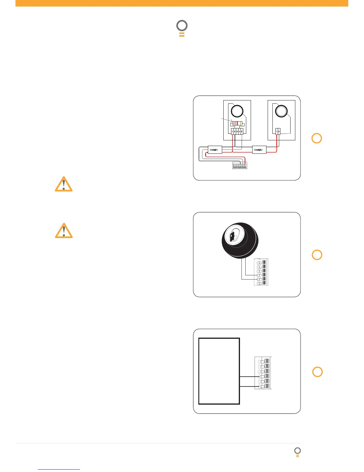
Step 21 - key switch connection
Gdo-11v1 Has The Input To Connect Bell Switch
Or Key Switch To Open Or Close The Door.
Connect The Key/bell Switch As Per Diagram (Fig.
47).
Step 22 - Auxiliary out put
The auxiliary output can be used to control alarm or
another garage door opener. A valid transmission
from the pre-coded transmitter will cause the
auxiliary out put to pulse for approximately 1
(one) second. The maximum DC voltage must not
exceed 35 volts DC. Maximum current must not
exceed 80 ma.(Fig. 48).
a.
b.
c.
P.E. Beams